Device and method for producing biological fuel oil by quickly cracking biomass

A biofuel and biomass technology, which is applied in the preparation of biofuels, liquid hydrocarbon mixtures, and the petroleum industry, can solve the problems of heat carrier heating temperature without precise temperature control, poor continuity of actual production, and low energy utilization. Achieve the effect of simple structure, favorable industrial production and large production capacity

Inactive Publication Date: 2011-04-27
NORTHEAST FORESTRY UNIVERSITY
View PDF3 Cites 11 Cited by
  • Summary
  • Abstract
  • Description
  • Claims
  • Application Information

AI Technical Summary

Problems solved by technology

[0004] The present invention aims to solve the problem of low energy utilization rate, high operation cost and poor continuity of actual production in the existing biomass thermal cracking process; in addition, in the existing large biomass thermal cracking process devices, the heating temperature of the heat carrier mostly does not have the function of precise temperature regulation To solve the problem, a device and method for producing biofuel by rapid pyrolysis of biomass are provided

Method used


Image

  • Device and method for producing biological fuel oil by quickly cracking biomass
  • Device and method for producing biological fuel oil by quickly cracking biomass

Examples


specific Embodiment approach 1

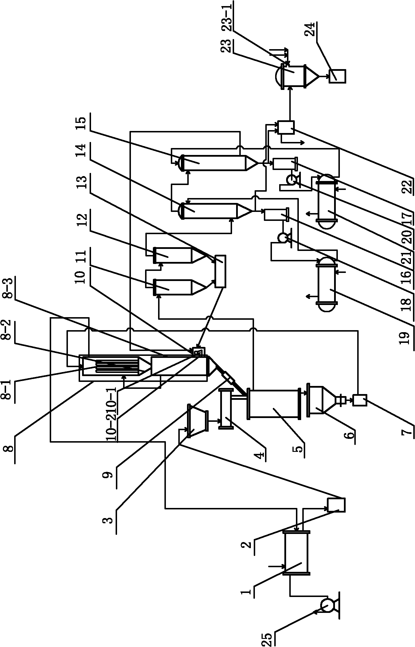
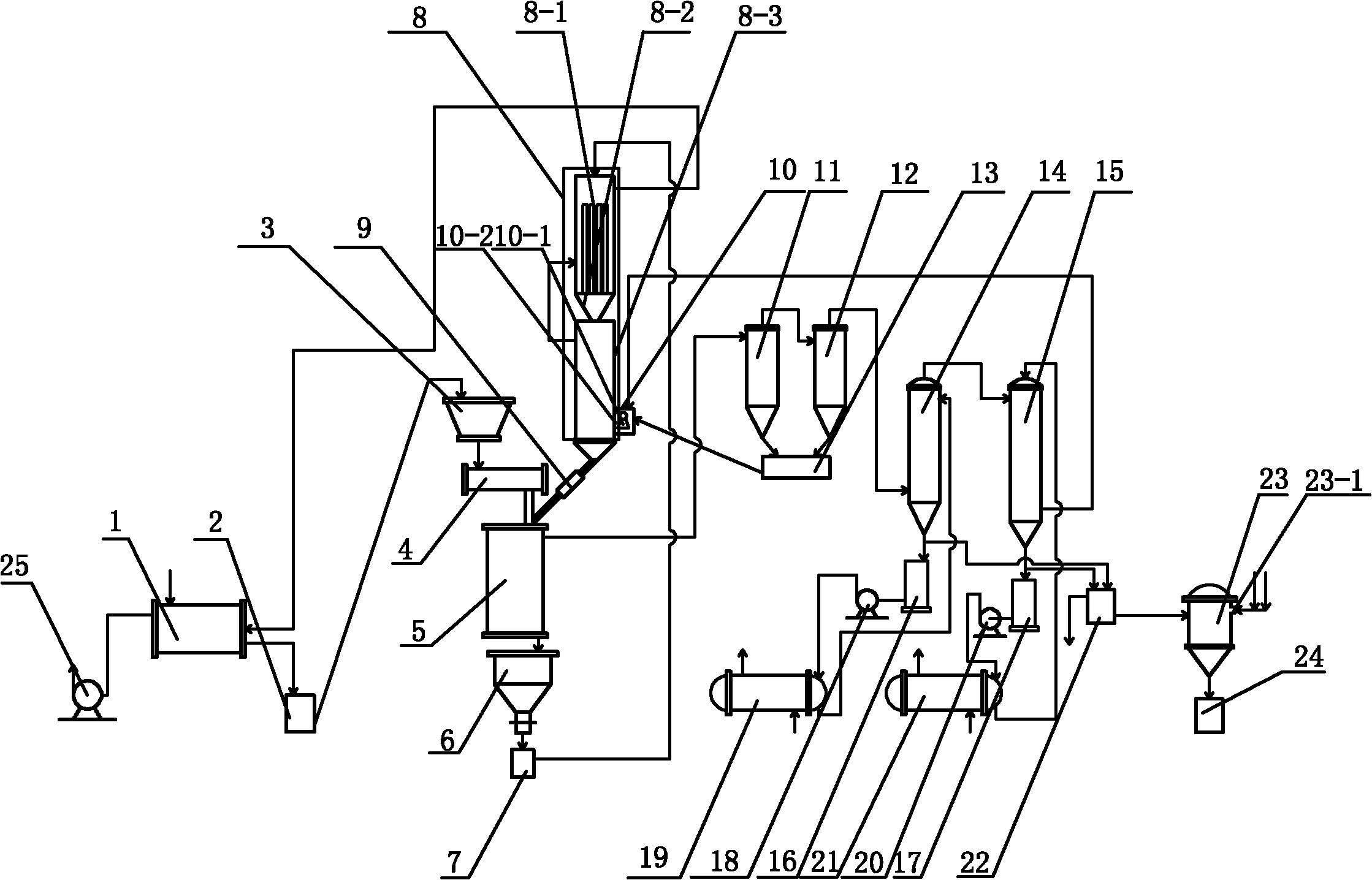
[0018] Specific implementation mode one: combine figure 1 Description of this embodiment, the device of this embodiment includes a dryer 1, a powder mill 2, a storage hopper 3, a feeding mechanism 4, a cracking reactor 5, a heat carrier collection box 6, a heat carrier lifting bucket 7, and a heat carrier heating device 8 , Heat carrier temperature precision control device 9, heat energy supply device 10, primary separator 11, secondary separator 12, carbon collection box 13, primary condenser 14, secondary condenser 15, first condensate storage tank 16 , the second condensate storage tank 17, the first pump 18, the first heat exchanger 19, the second pump 20, the second heat exchanger 21, the biofuel product collection box 22 and the induced draft fan 25, the drying machine 1 and the pulverizer The machine 2 is connected, the powder making machine 2 is connected with the storage hopper 3, the storage hopper 3 is connected with the feed port of the cracking reactor 5 through t...

specific Embodiment approach 2

[0019] Specific implementation mode two: combination figure 1 To illustrate this embodiment, the condensate outlet end of the primary condenser 14 of this embodiment communicates with the first condensate storage tank 16, and the first condensate storage tank 16 communicates with the first heat exchanger 19 through the first pump 18, The first heat exchanger 19 communicates with the condensate inlet port of the primary condenser 14, the condensate outlet port of the secondary condenser 15 communicates with the second condensate storage tank 17, and the second condensate storage tank 17 passes through the second pump 20 communicates with the second heat exchanger 21, the second heat exchanger 21 communicates with the condensate inlet port of the secondary condenser 14, and the biofuel outlet ports of the primary condenser 14 and the secondary condenser 15 are connected with the biofuel product The collection box 22 is connected, and the flue gas generated in the heat energy sup...

specific Embodiment approach 3

[0020] Specific implementation mode three: combination figure 1Describe this embodiment, the thermal energy supply device 10 of this embodiment is made up of noncondensable gas burner 10-1 and combustion chamber 10-2, and noncondensable gas burner 10-1 is arranged in the combustion chamber 10-2, and thermal energy supply device 10 is arranged under the side of the heat carrier heating device 8 . Other components and connections are the same as those in the first embodiment.

[0021] Specific implementation mode four: combination figure 1 Describe this embodiment, the heat carrier heating device 8 of this embodiment is made up of heating pipe 8-1, heat carrier flow control valve 8-2 and a group of inclined partitions 8-3, and heating pipe 8-1 is arranged at the heat carrier heating Above the device 8, a group of inclined partitions 8-3 are installed below the heat carrier heating device 8, and the heating pipe 8-1 communicates with a group of inclined partitions 8-3 through t...


PUM

PropertyMeasurementUnit
lengthaaaaaaaaaa
lengthaaaaaaaaaa
heating valueaaaaaaaaaa

Abstract

The invention discloses a device and a method for producing biological fuel oil by quickly cracking biomass, relates to a device and a method for producing biological fuel oil and aims to solve the problems of low energy utilization ratio, high operating cost and poor practical production continuity existing in the conventional biomass thermal cracking process and the problem of the absence of accurate heat carrier heating temperature regulating function in the conventional biomass thermal cracking process device. In the scheme of the device, the bottom of a heat carrier heating device is communicated with a heat carrier inlet end of a cracking reactor through an accurate heat carrier temperature control device; the cracking reactor is communicated with a separator; the separator is communicated with a condenser; the condenser is communicated with a heat energy supply device; and the heat energy supply device is communicated with the heat carrier heating device. In the scheme of the method, products produced by the thermal cracking reaction of biomass powder comprise thermal cracking gas and carbon; a heat carrier enters a heat carrier collecting box; and uncondensed thermal cracking gas enters a non-condensable gas burner to burn, and then smoke gas is produced and enters the heat carrier heating device. The device and the method are used for producing biological fuel oil.

Description

technical field [0001] The invention relates to a device and method for producing biofuel. Background technique [0002] Bio-oil produced from biomass is a new type of liquid energy that is extremely versatile and can replace petroleum to a certain extent, and is renewable. It can be directly used as fuel instead of petroleum to a certain extent, and it can also be mixed and emulsified with gasoline and diesel in a certain proportion to make a clean and environmentally friendly "bio-fuel + diesel" mixed emulsified fuel. Experiments have shown that this fuel can Used on ordinary diesel engines, it not only saves oil, but also reduces greenhouse gas emissions caused by burning oil in large quantities. [0003] Biomass pyrolysis refers to the rapid heating of biomass to pyrolyze biomass in the absence of oxygen or anoxic conditions to produce pyrolysis gas and charcoal, and rapid cooling of pyrolysis gas to convert condensable components into liquid biofuels the process of. ...

Claims


Application Information

Patent Timeline
Patent Type & Authority Applications(China)
IPC IPC(8): C10G1/00C10B53/02C10B57/10C10B57/00C10B49/00
CPCY02E50/14Y02E50/10
Inventor 谭文英王述洋徐凯宏曹有为李滨
Owner NORTHEAST FORESTRY UNIVERSITY
Why Eureka
Try Eureka