
Drying device and method for drying a compressed gas

Pending Publication Date: 2022-06-23
ATLAS COPCO AIRPOWER NV
View PDF0 Cites 0 Cited by
  • Summary
  • Abstract
  • Description
  • Claims
  • Application Information

AI Technical Summary

Benefits of technology

The patent text describes a system that regulates the flow through a venturi ejector, which helps to reduce energy loss and pressure drop. By controlling the flow, less regeneration gas is sucked in, resulting in lower pressure drop.

Problems solved by technology

When a vessel will dry, it will take up the moisture from the compressed gas to be dried, such that the desiccant becomes saturated.
A disadvantage is that in such venturi ejector a relatively large pressure drop can take place.

Method used


Image

  • Drying device and method for drying a compressed gas
  • Drying device and method for drying a compressed gas

Examples


Embodiment Construction

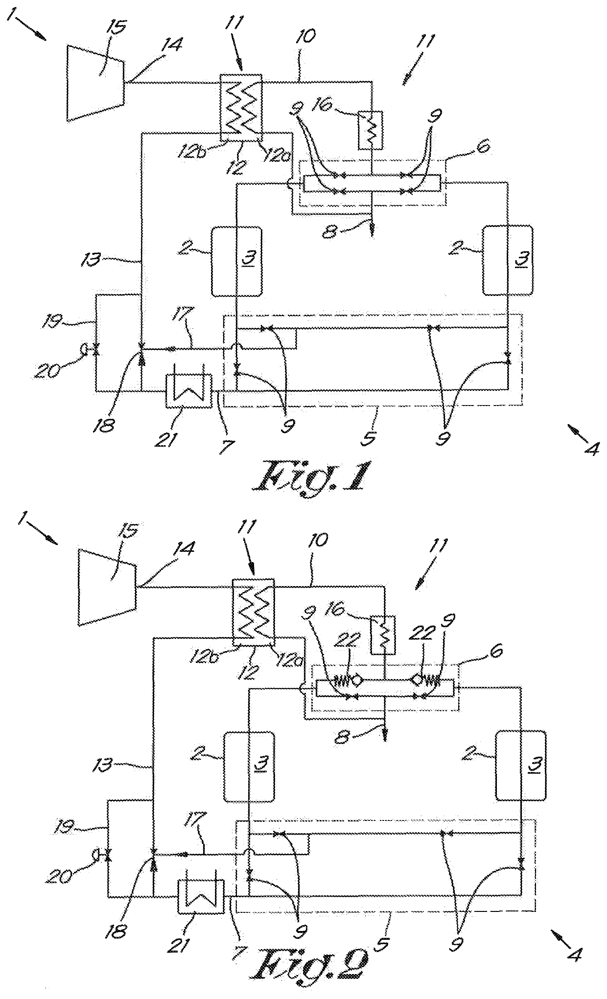
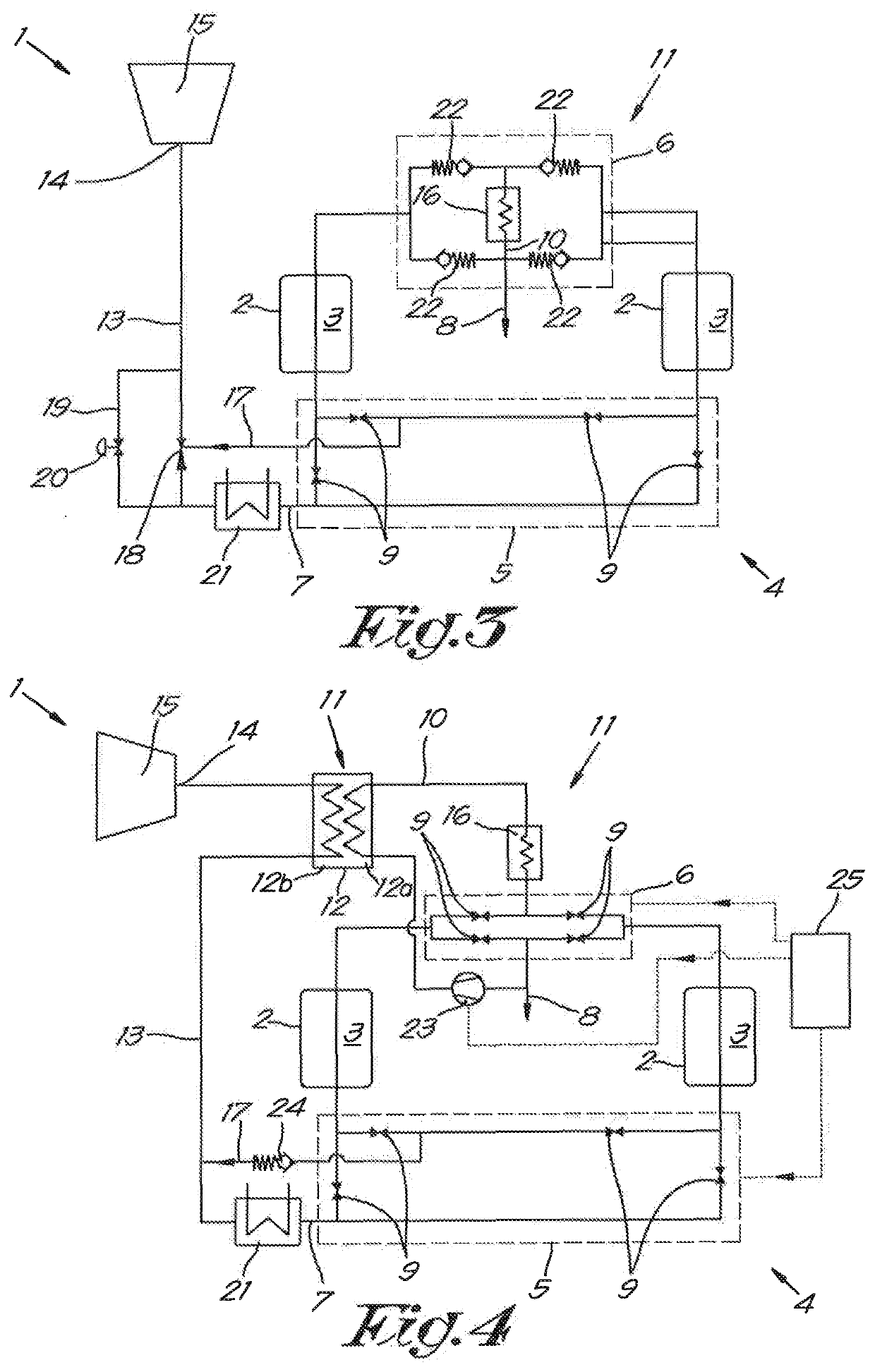
[0045]The drying device 1 according to the invention for drying compressed gas schematically shown in FIG. 1 essentially comprises two vessels 2 containing a regenerable desiccant 3.

[0046]This regenerable desiccant 3 is also called desiccant.

[0047]Of course it is possible there are more than two vessels 2.

[0048]The drying device 1 further comprises a valve system 4 that consists of a first valve block 5 and a second valve block 6.

[0049]The first valve block 5 will connect the vessels 2 with an inlet 7 for compressed gas to be dried, while the second valve block 6 will connect the vessels 2 to an outlet 8 for dried compressed gas.

[0050]Said valve blocks 5, 6 are a system of different pipes and valves that can be regulated such that at least one vessel 2 is always being regenerated or possibly cooled, while the other vessel 2 or the other vessels 2 dry the compressed gas, whereby by regulating the valve system 4 the vessels 2 will each in turn dry compressed gas.

[0051]In this case eac...


PUM


Abstract

Drying device for drying compressed gas which includes at least two vessels with regenerable desiccant and an adjustable valve system which is such that a vessel can dry compressed gas, while the other vessel is being regenerated, whereby by regulating the valve system, the vessels can each in turn dry gas. The drying device includes a regeneration pipe for supplying a regeneration gas which runs from an outlet for dried gas to the valve system, and in which heating means are provided, whereby the drying device is provided with a return pipe for returning the regeneration gas to an inlet, running from the valve system to an inlet pipe which connects to said inlet and in which a venturi ejector is mounted, to which said return pipe is connected, and that regulating means are provided for regulating the flow of gas going through the venturi ejector.

Description

BACKGROUND OF THE INVENTION[0001]In particular, the invention relates to drying devices which are provided with an inlet for compressed gas to be dried and an outlet for dried compressed gas, whereby the drying device comprises at least two vessels containing a regenerable desiccant and an adjustable valve system connecting said inlet and outlet to said vessels, whereby the adjustable valve system is configured such that at least one vessel can dry compressed gas, while the other vessel is being regenerated, and that by regulating the valve system, the vessels can each in turn dry compressed gas.[0002]Regenerable desiccant refers to a desiccant that is able to extract moisture from a gas by means of adsorption and which, when saturated with moisture, can be dried by sending a so-called regeneration gas through it. This process is also called regeneration of the desiccant. Typically, the regeneration gas is a warm gas.[0003]Although there is mention here of the principle of adsorptio...

Claims


Application Information

Patent Timeline
IPC IPC(8): B01D53/26B01D53/04
CPCB01D53/261B01D53/0438B01D2259/402B01D2259/4009B01D2259/40003F04B39/16F04C29/04B01D53/26
Inventor HERMANS, HANS MARIA KAREL
Owner ATLAS COPCO AIRPOWER NV
Learn More