Plate heat exchanger

Active Publication Date: 2015-10-22
DANFOSS MICRO CHANNEL HEAT EXCHANGER JIAXING
View PDF5 Cites 8 Cited by
  • Summary
  • Abstract
  • Description
  • Claims
  • Application Information

AI Technical Summary

Benefits of technology

[0030]2. provision of different heat exchange regions in the channels on the basis of heat-transfer mechanism correlated to refrigerant evaporation, to reinforce the heat transfer;
[0031]3. reduction of difficulties on productions and manufacturing and widening of practical application scopes a

Problems solved by technology

For a paralleled-channel heat exchanger (evaporator), especially, for a plate heat exchanger and a micro channel heat exchanger, mal-distribution of the refrigerant is a worldwide technical problem.
Generally, the refrigerant entered into the heat exchanger is in a two-phase manner, since complicated application conditions and two-phase flows, it is hard to achieve uniform distr

Method used


Image

  • Plate heat exchanger
  • Plate heat exchanger
  • Plate heat exchanger

Examples


Example

1st Embodiment

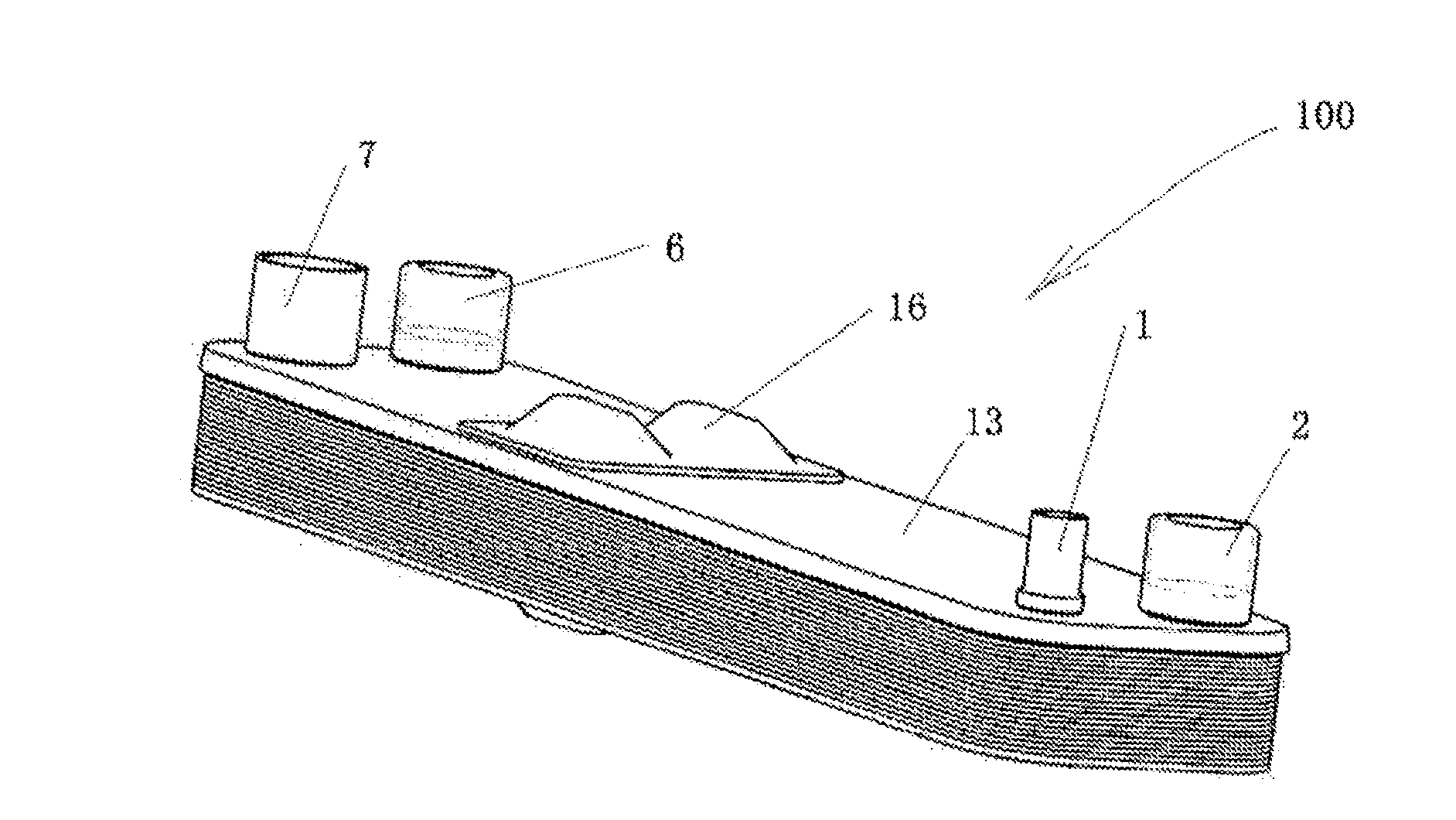
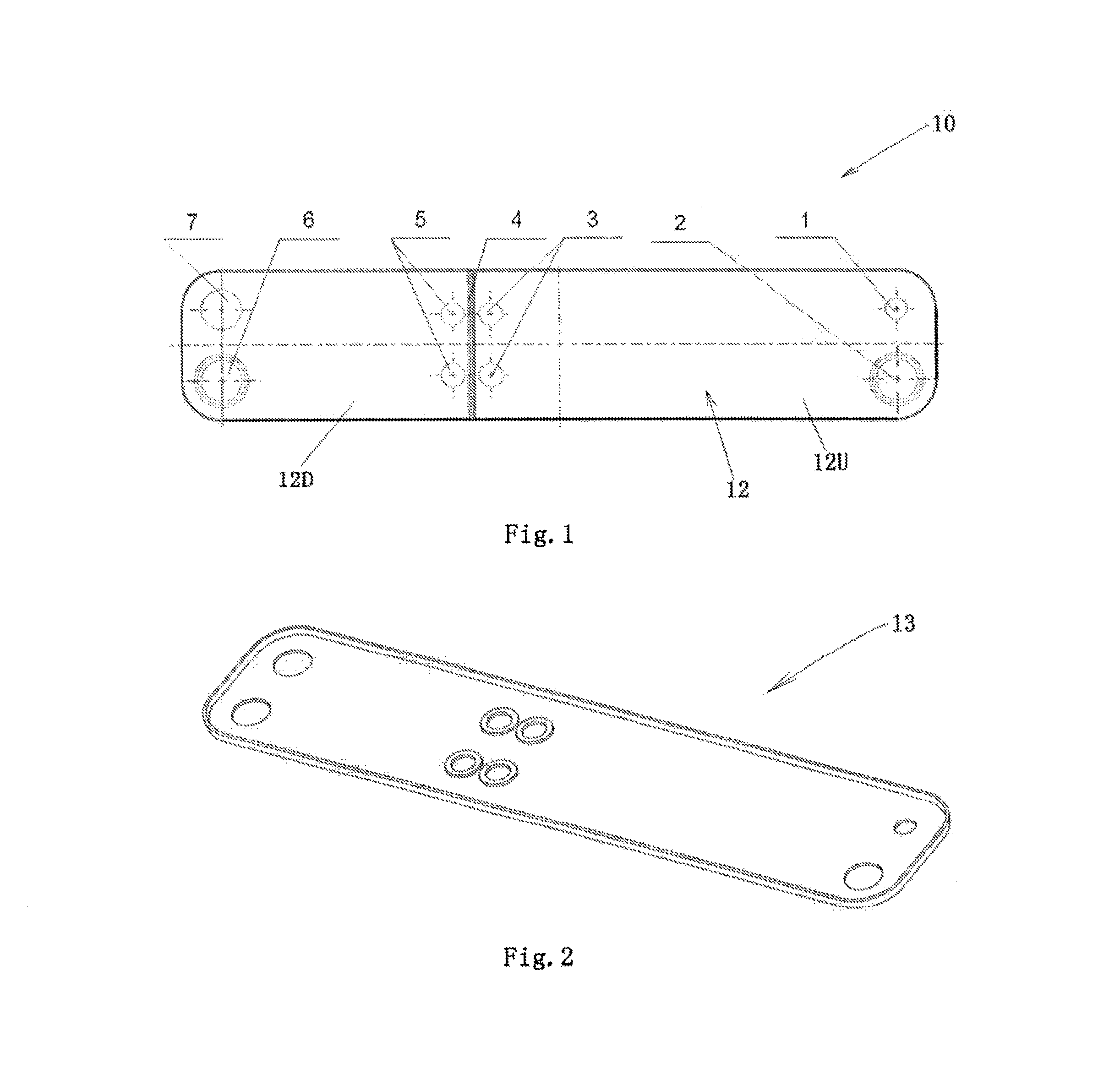
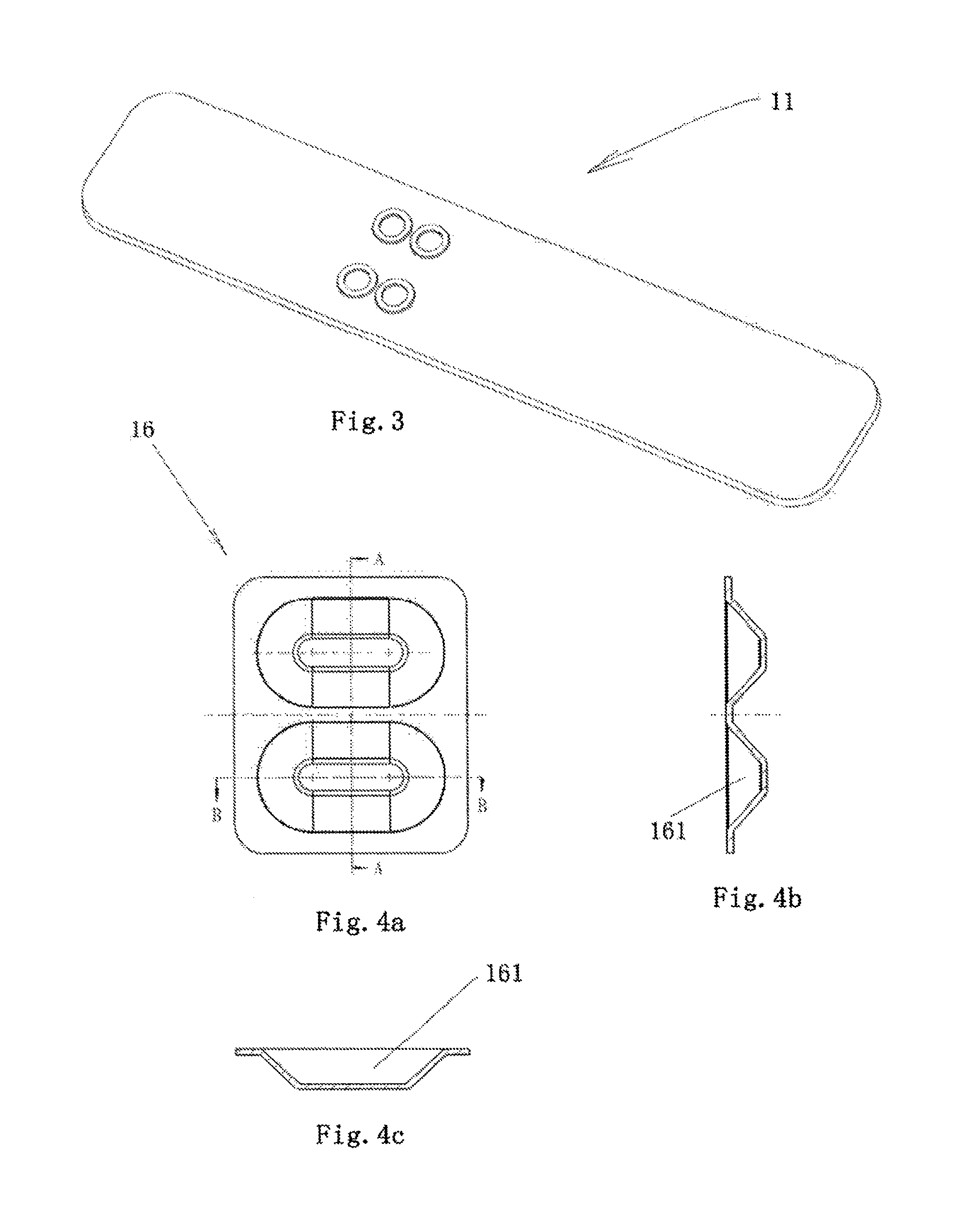
[0051]Referring to FIGS. 1-8, the plate heat exchanger 100 according to the embodiment of the present invention comprises heat exchange plates 10 each forms one or more first fluid channels 12 and one or more second fluid channels and end plates 11 and 13. The ends plates 11 and 13 are provided on the outer side of the plate heat plate 10.

[0052]As shown in FIGS. 2 and 3, each of the ends plates 11 and 13 has the same through holes as the corresponding side surface of the heat exchange plate 10. The heat exchange plate 10 may be integral. The plate heat exchanger 100 further comprises a first fluid inlet 1, a first fluid outlet 7, a second fluid outlet 2 (for a reverse-flow evaporator) and a second fluid inlet 6 (for a reverse-flow evaporator). First fluid, such as refrigerant, flows in one first fluid channel 12, and, second fluid, such as water, flows in one second fluid channel. Aperture size of the first fluid inlet 1 may be less than that of the first fluid outlet ...

Example

3rd Embodiment

[0071]The present invention is also suitable for a dual circuit evaporator. FIG. 11 shows a schematic view of a dual circuit refrigerant plate heat exchanger 100. The plate heat exchanger 100 has two refrigerant circulating circuits which are heated commonly by one water circulating system. In FIG. 11, W indicates a water circuit, R1 indicates a first refrigerant circuit, and, R2 indicates a second refrigerant circuit. The present invention provides a solution for such application as shown in FIG. 12. For a single side-flow channel, number 1 denotes an inlet for a first refrigerant (first fluid inlet), numbers 3 and 5 denote upstream and downstream communication ports (an outlet of the first fluid channel upstream portion 12U and an inlet of the first fluid channel downstream portion 12D), number 7 denotes an outlet for the first refrigerant (first fluid outlet); number 1′ denotes an inlet for a second refrigerant (first fluid inlet), number 7′ denotes an outlet for th...


PUM


Abstract

The prevent invention provides a plate heat exchanger. The plate heat exchanger comprises heat exchange plates each forms one or more first fluid channels and one or more second fluid channels. The one or more first fluid channels each has a fluid channel upstream portion and a fluid channel downstream portion separated from the fluid channel upstream portion, wherein the fluid channel upstream portion is fluidly communicated via a fluid communication device with the fluid channel downstream portion. The plate heat exchanger according to the present invention achieves uniform distribution of the refrigerant while being independent of the distributors, and, provides different heat exchange regions in the channels on the basis of heat-transfer mechanism correlated to refrigerant evaporation, to reinforce the heat transfer. The plate heat exchanger, without the distributors, according to the present invention not only reduces difficulties on productions and processes, but also, widens practical application scopes and conditions. In addition, as there is no distributor in the plate heat exchanger, compared with other similar products, the refrigerant stream has a lower total pressure drop, which brings more spaces for type selection of the expansion valve.

Description

CROSS-REFERENCE TO RELATED APPLICATION[0001]This application is entitled to the benefit of and incorporates by reference subject matter disclosed in the International Patent Application No. PCT / CN2013 / 088503 filed on Dec. 4, 2013 and Chinese Patent Application 201210535175.3 filed Dec. 10, 2012.BACKGROUND OF THE INVENTION[0002]1. Field of the Invention[0003]The present invention relates to a plate heat exchanger.[0004]2. Description of the Related Art[0005]For a paralleled-channel heat exchanger (evaporator), especially, for a plate heat exchanger and a micro channel heat exchanger, mal-distribution of the refrigerant is a worldwide technical problem. Generally, the refrigerant entered into the heat exchanger is in a two-phase manner, since complicated application conditions and two-phase flows, it is hard to achieve uniform distribution of the refrigerant. In most cases, excess liquid refrigerant will flow into some of the channels while excess gaseous refrigerant will flow into so...

Claims


Application Information

Patent Timeline
IPC IPC(8): F28D7/00
CPCF28D7/0066F28D9/005F28D9/0093F28F9/026F28F9/22F28F13/06F28D9/0037F28D9/0056F28F3/02F28F9/001F28D9/0043F28F3/08F28F3/086F25C1/12
Inventor PERSSON, LARS
Owner DANFOSS MICRO CHANNEL HEAT EXCHANGER JIAXING
Why Eureka
Try Eureka