Jet ejector system and method

Inactive Publication Date: 2005-03-24
TERRABON ADVE +1
View PDF10 Cites 7 Cited by
  • Summary
  • Abstract
  • Description
  • Claims
  • Application Information

AI Technical Summary

Benefits of technology

Embodiments of the invention provide a number of technical advantages. Embodiments of the invention may include all, some, or none of these advantages. An advantage of a jet ejector system according to one embodiment of the invention is that it blends gas streams of similar pressures; therefore, the velocity of each gas stream is similar. This leads to high efficiencies, even using traditional jet ejectors. The efficiency may be improved further by improving the design of the jet ejector.
In other embodiments, a heat exchanger is designed to facilitate a lower pressure drop than existing heat exchangers at low cost. Such a heat exchanger may include a plurality of plates (or sheets) inside a tube. The plates may be made of any suitable material; however, for some embodiments in which corrosion is a concern, the plates may be made of a suitable polymer.

Problems solved by technology

This leads to high efficiencies, even using traditional jet ejectors.

Method used


Image

  • Jet ejector system and method
  • Jet ejector system and method
  • Jet ejector system and method

Examples


Embodiment Construction

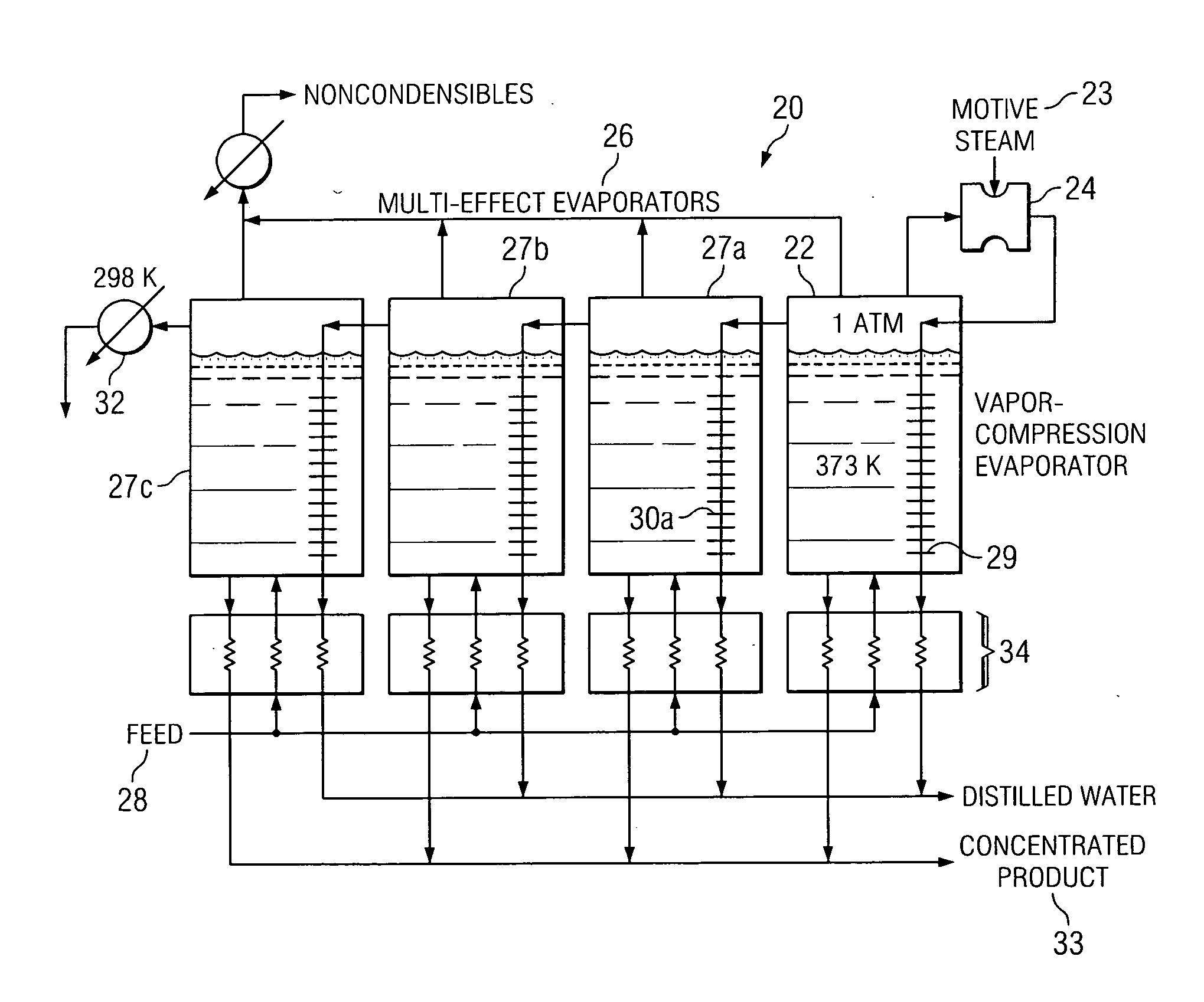
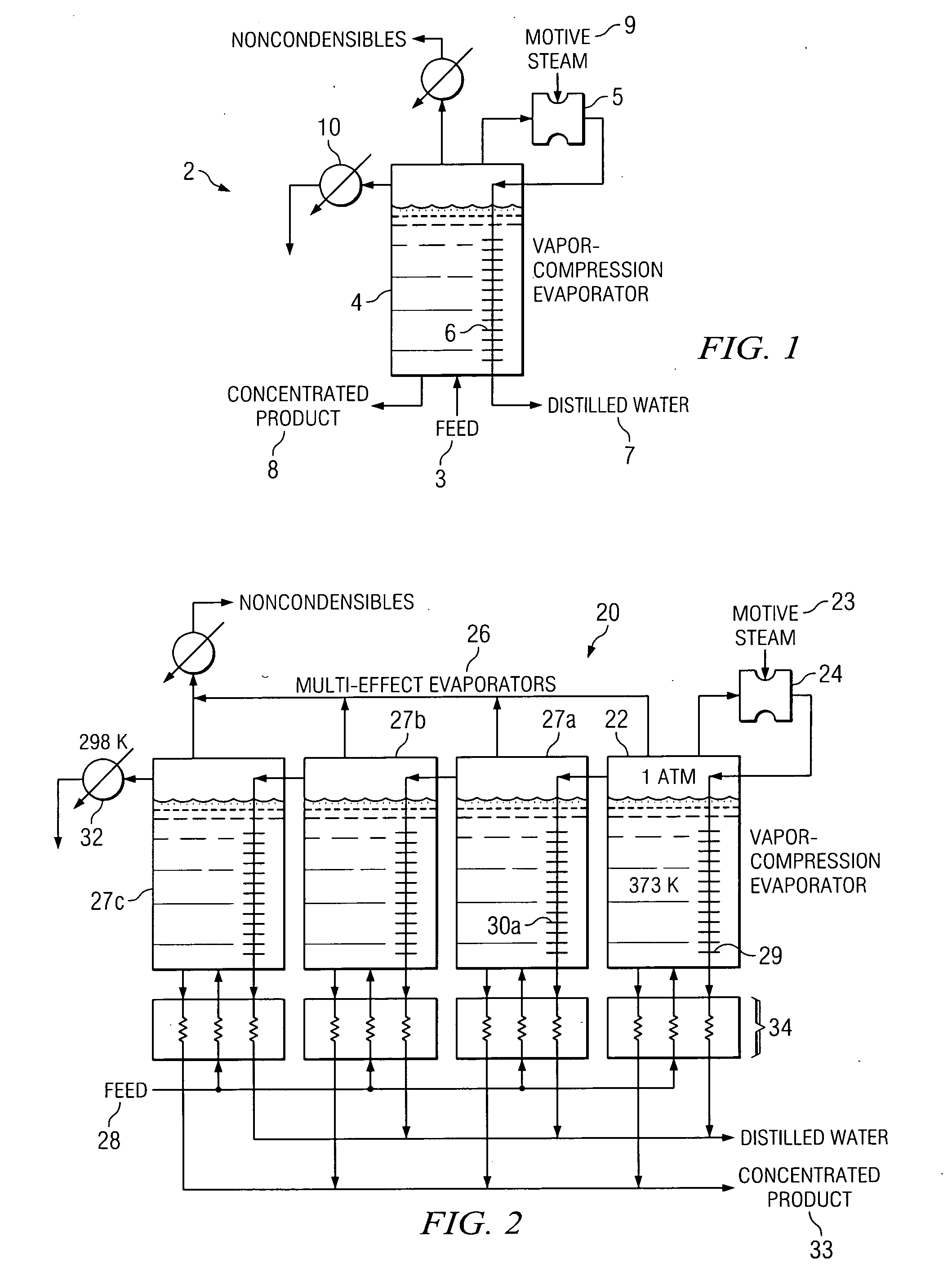
FIG. 1 illustrates a low-pressure vapor-compression evaporator system 2 performing desalination of salt water. A salt-containing feed 3 flows into an evaporator tank 4, which in this embodiment is operated under vacuum. Although, in the illustrated embodiment, feed 3 is a salt-containing feed, a sugar-containing feed or suitable feed is also contemplated by the present invention. The salt-containing feed 3 boils, producing low-pressure vapors. These vapors are removed from evaporator tank 4 using a jet ejector 5. The pressurized vapors exiting jet ejector 5 flow into a heat exchanger 6, where they condense. Because of the interaction of heat exchanger 6 and evaporator tank 4, the heat of condensation provides the heat of evaporation needed by the salt-containing feed 3. Distilled liquid water 7 is recovered from heat exchanger 6 in any suitable manner, and concentrated salt solution 8 is removed from evaporator tank 4 using any suitable devices. The motive steam 9 added to jet eject...


PUM


Abstract

According to one embodiment of the invention, a jet ejector method includes providing a primary jet ejector having a primary inlet stream, coupling one or more secondary jet ejectors to the primary jet ejector such that all of the jet ejectors are in a cascaded arrangement, bleeding off a portion of the primary inlet stream and directing the portion of the primary inlet stream to the secondary jet ejector that is closest to the primary jet ejector in the cascaded arrangement, and directing a motive fluid into the secondary jet ejector that is farthest from the primary jet ejector in the cascaded arrangement. The method further includes, at each secondary jet ejector, receiving at least some of the portion of the primary inlet stream and at least some of the motive fluid to create respective mixtures within the secondary jet ejectors, and at each secondary jet ejector, directing at least a portion of the respective mixture to adjacent jet ejectors in the cascaded arrangement.

Description

TECHNICAL FIELD OF THE INVENTION The present invention relates generally to the field of jet ejectors and, more particularly, to an improved, ultra-high efficiency jet ejector system and method. BACKGROUND OF THE INVENTION Typical steam jet ejectors feed high-pressure steam, at relatively high velocity, into the jet ejector. Steam is usually used as the motive fluid because it is readily available; however, an ejector may be designed to work with other gases or vapors as well. For some applications, water and other liquids are sometimes good motive fluids as they condense large quantities of vapor instead of having to compress them. Liquid motive fluids may also compress gases or vapors. The motive high-pressure steam enters a nozzle and issues into the suction head as a high-velocity, low-pressure jet. The nozzle is an efficient device for converting the enthalpy of high-pressure steam or other fluid into kinetic energy. A suction head connects to the system being evacuated. The...

Claims


Application Information

Patent Timeline
IPC IPC(8): F04F5/46F04F5/54F28D9/00
CPCF04F5/466F28D9/0037F04F5/54F04F5/467
Inventor HOLTZAPPLE, MARK T.NOYES, GARY P.RABROKER, GEORGE A.
Owner TERRABON ADVE
Why Eureka
Try Eureka