Improved architecture of a turbomachine with counter-rotating turbine

a technology of counter-rotating turbine and turbomachine, which is applied in the direction of engines/engines, mechanical apparatus, engine components, etc., can solve the problems of significant bending stress, appearance of clearance between the rotors, and some drawbacks of the structure, so as to reduce the length of the second shaft, reduce the appearance or modification, and less sensitive to gyroscopic effects

Pending Publication Date: 2022-06-23
SN DETUDE & DE CONSTR DE MOTEURS DAVIATION S N E C M A
View PDF5 Cites 0 Cited by
  • Summary
  • Abstract
  • Description
  • Claims
  • Application Information

AI Technical Summary

Benefits of technology

[0023]The median plane, or geometric center, designates the center, along the axis of rotation, of the total length of the turbine. According to this configuration, the turbine is less sensitive to gyroscopic effects. In other words, this position of the first and second bearings allows ensuring that the bending movements of the first and second shafts, resulting in rotations of the rotors about an axis perpendicular to the axis of rotation of the turbine, will generate mainly axial displacements at the tops of the blades, and little radial displ

Problems solved by technology

However, this architecture has some drawbacks.
In particular, the position of the bearing guiding the second shaft forces the latter to be very long, and is therefore subject to significant bending stresses.
However, a significant bending of the second shaft relative to the first shaft can cause the appearance of clearances between the rotors, or the modification of already existing clearances.
Moreover, the bearings of the first and second shafts being carried by different structures (upstream casing for the first shaft and downstream casing for the second shaft), the local deformations of these casings, caused by expansions, distortions or gyroscopic

Method used


Image

  • Improved architecture of a turbomachine with counter-rotating turbine
  • Improved architecture of a turbomachine with counter-rotating turbine

Examples


Embodiment Construction

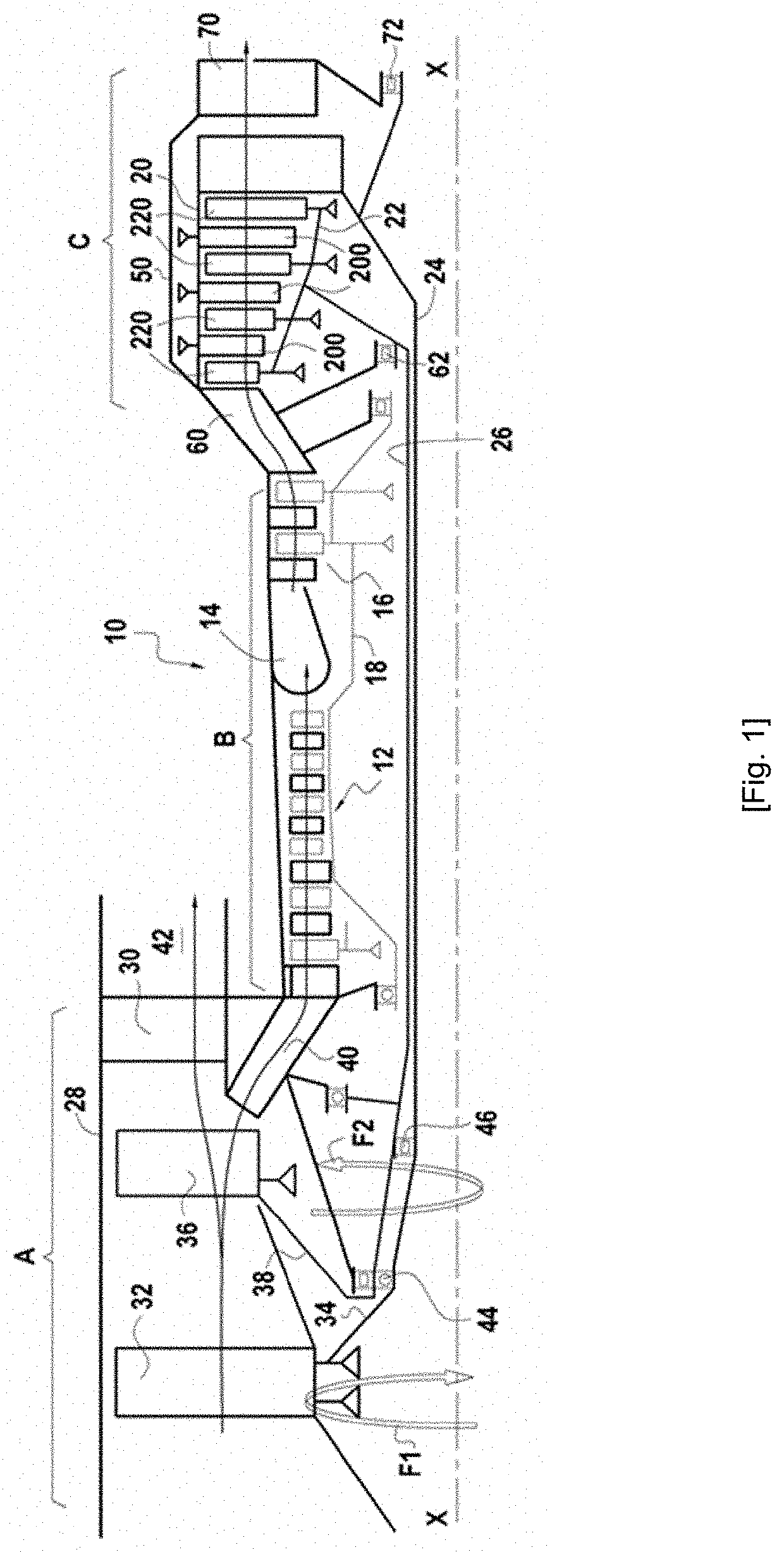
[0036]Referring to FIG. 1, a turbomachine 10 with counter-rotating fans includes a longitudinal axis X-X. From upstream to downstream along the direction of flow of the gases in the turbomachine (represented by the black arrow), the turbomachine 10 essentially comprises three parts: an upstream module A (or fan section), an intermediate module B (or high-pressure body) and a downstream module C (or low-pressure turbine section).

[0037]The three parts A, B and C of the turbomachine are modular, that is to say they each form a single assembly and can each be replaced by being separated from the other parts of the turbomachine.

[0038]In a manner well known per se, the high-pressure body B comprises a gas generator for producing combustion gases. This gas generator comprises a compressor 12, a combustion chamber 14 and a high-pressure turbine 16.

[0039]The air compressed by the compressor 12 is mixed with the fuel in the combustion chamber 14 before being burned therein. The thus produced ...


PUM


Abstract

Counter-rotating turbine of a turbomachine extending about an axis of rotation and comprising an inner rotor rotating about the axis of rotation, and comprising at least one inner movable blade rotatably supported by a first shaft, an outer rotor rotating about the axis of rotation in a direction opposite to the inner rotor, and comprising at least one outer movable blade rotatably supported by a second shaft coaxial with the first shaft, the first and second shafts extending axially from upstream to downstream of the turbine, wherein the first shaft is guided in rotation by a first bearing disposed between the first shaft and an upstream casing of the turbine, and the second shaft is guided in rotation by a second bearing disposed between the second shaft and said upstream casing of the turbine.

Description

TECHNICAL FIELD[0001]The present disclosure relates to the field of turbomachines. More specifically, the present disclosure relates to a counter-rotating turbine of a turbomachine, and a turbomachine comprising such a turbine.PRIOR ART[0002]An aircraft turbomachine generally comprises, from upstream to downstream in the direction of flow of the gases, a fan, a low-pressure compressor, a high-pressure compressor, a combustion chamber, a high-pressure turbine and a low-pressure turbine. The rotor of the low-pressure compressor is driven by the rotor of the low-pressure turbine, and the rotor of the high-pressure compressor is driven by the rotor of the high-pressure turbine.[0003]In order to improve the engine efficiency, the aircraft turbomachines can be equipped with a counter-rotating turbine, instead of the low-pressure turbine. The counter-rotating turbine comprises an inner rotor, called fast rotor, connected to a first turbine shaft, and configured to rotate in a first directi...

Claims


Application Information

Patent Timeline
IPC IPC(8): F02C3/067F02C7/06
CPCF02C3/067F02C7/06F05D2260/98F05D2240/60F05D2240/54F04D19/024
Inventor GALLET, FRANCOIS
Owner SN DETUDE & DE CONSTR DE MOTEURS DAVIATION S N E C M A
Why Eureka
Try Eureka