Eureka AIR delivers breakthrough ideas for toughest innovation challenges, trusted by R&D personnel around the world.

Fuel cell system and method for controlling fuel cell system

Active Publication Date: 2022-06-23
TOYOTA JIDOSHA KK
View PDF5 Cites 0 Cited by
  • Summary
  • Abstract
  • Description
  • Claims
  • Application Information

AI Technical Summary

Benefits of technology

The present disclosure provides a fuel cell system that includes a fuel cell and a secondary cell, along with a fuel cell step-up converter and a secondary cell step-up converter. The system also includes a control device that is responsible for controlling the fuel cell and secondary cell step-up converters to ensure efficient operation of the fuel cell system. The control device can interrupt the electrical connection between the fuel cell system and the secondary cell to achieve higher output voltage during the continuity control, which allows the user to achieve the desired output even when the output requested by the user is higher than the output of the secondary cell. The technical effect of this patent is to provide a fuel cell system that can easily control the output voltage and maintain higher efficiency during the continuity control.

Problems solved by technology

In a state in which the secondary cell step-up converter has broken down and is unable to step up the voltage, the output voltage of the fuel cell becomes lower than the output voltage that is obtained under normal conditions, which sometimes makes it impossible for a user to obtain a desired output.

Method used


Image

  • Fuel cell system and method for controlling fuel cell system
  • Fuel cell system and method for controlling fuel cell system
  • Fuel cell system and method for controlling fuel cell system

Examples


first embodiment

A. First Embodiment

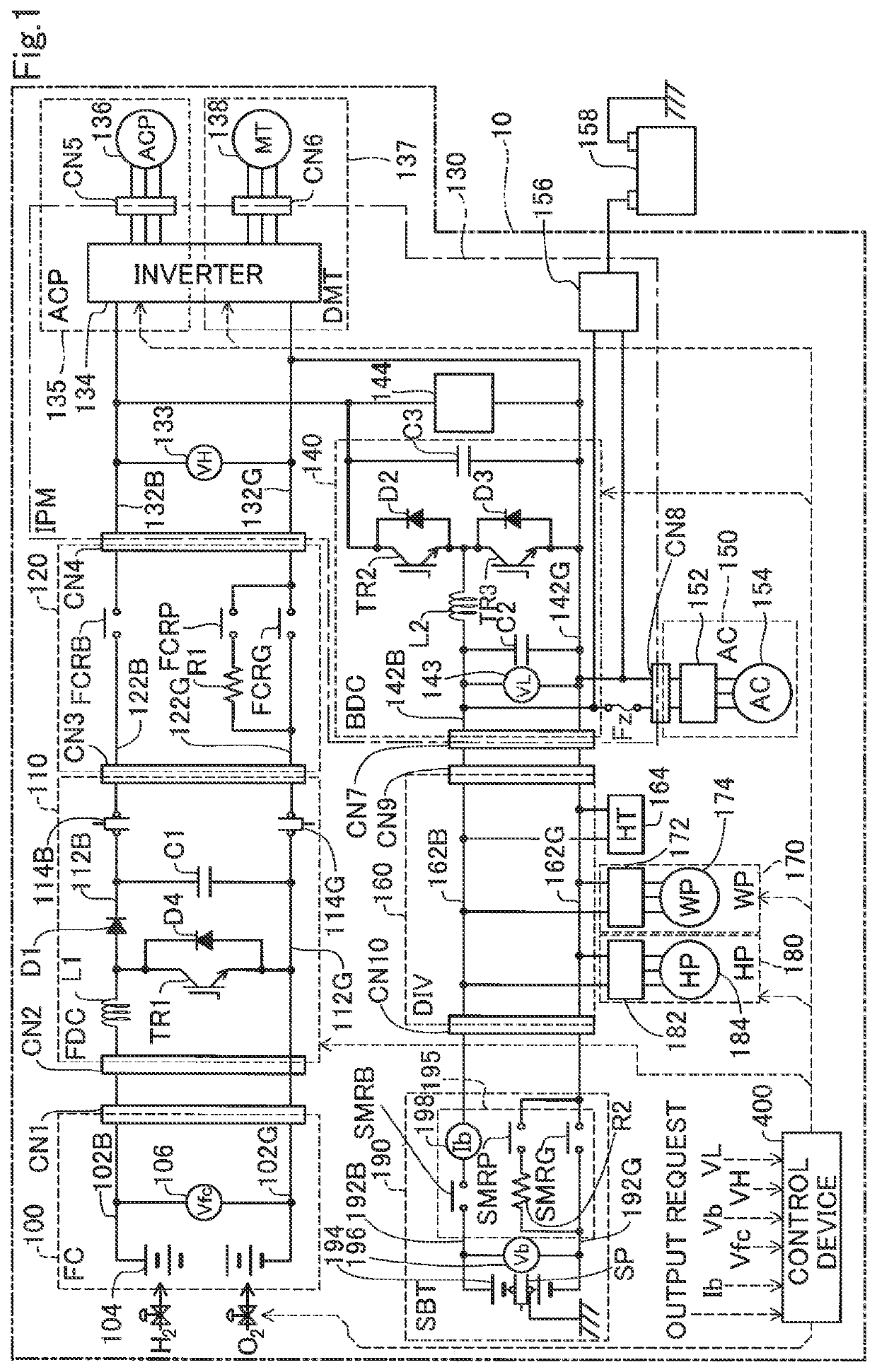
[0009]FIG. 1 is an explanatory diagram showing the schematic configuration of a fuel cell system 10. The fuel cell system 10 is installed in, for example, a fuel-cell vehicle using a fuel cell as a drive source. The fuel cell system 10 includes a fuel cell unit 100, a fuel-cell step-up converter unit 110 (hereinafter also referred to as an “fuel cell step-up converter 110”), a fuel cell relay unit 120 (hereinafter also referred to as an “fuel cell relay 120”), an intelligent power module unit 130 (hereinafter also referred to as an “IPM 130”), an air conditioner unit 150, a branch unit 160, a water pump unit 170, a hydrogen pump unit 180, a secondary cell unit 190, and a control device 400. The IPM 130 includes an air compressor unit 135, a drive motor unit 137, and a DC-DC converter unit 140 (hereinafter also referred to as a “secondary cell step-up converter 140”). The fuel cell system 10 may be used in a household power source, stationary power generation, and ...

second embodiment

B. Second Embodiment

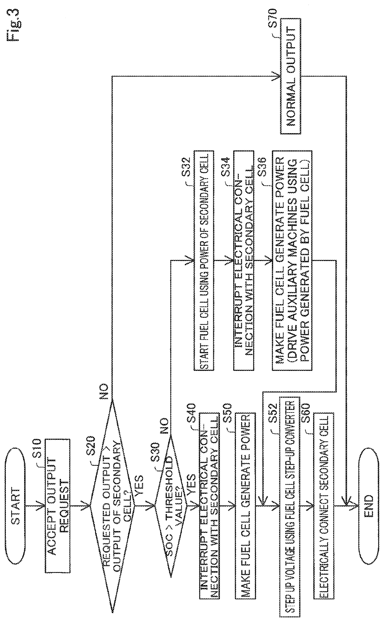
[0035]FIG. 3 is a flowchart showing a method for controlling the fuel cell system 10 as a second embodiment of the present disclosure. The method for controlling the fuel cell system 10 of the second embodiment differs from the method for controlling the fuel cell system 10 of the first embodiment in that Steps S32 to S36 are performed in place of Step S70 if the SOC of the secondary cell 194 is less than or equal to the threshold value in Step S30. Moreover, in the fuel cell system 10 of the first embodiment, power is supplied to the hydrogen pump unit 180 and the water pump unit 170 as the auxiliary machines only from the secondary cell 194 during the execution of the interruption control. On the other hand, the fuel cell system 10 of the second embodiment differs from the fuel cell system 10 of the first embodiment in that power is supplied to the hydrogen pump unit 180 and the water pump unit 170 also from the fuel cell 104 in addition to the secondary cell 1...


PUM


Abstract

A fuel cell system includes: a fuel cell; a fuel cell step-up converter having an input terminal, wherein the input terminal is connected to the fuel cell; a secondary cell; a secondary cell step-up converter having an input terminal an output terminal, wherein the input terminal is connected to the secondary cell. wherein the output terminal is connected to an output terminal of the fuel cell step-up converter; and a control device configured to control at least the fuel cell step-up converter and the secondary cell step-up converter to control the fuel cell system, wherein, the control device executes interruption control when the control device executes continuity control and an output of the fuel cell system is requested to be greater than an output of the secondary cell in the continuity control, wherein the continuity control is a control to control the secondary cell step-up converter to output an input voltage from the secondary cell without stepping up the input voltage, wherein the interruption control is a control to interrupt an electrical connection between the fuel cell system and the secondary cell.

Description

CROSS REFERENCE TO RELATED APPLICATIONS[0001]This application is based upon and claims the benefit of priority from Japanese Patent Application No. 2020-211335, filed Dec. 21, 2020, the entire contents of which are incorporated herein by reference.BACKGROUNDField[0002]The present disclosure relates to a fuel cell system and a method for controlling the fuel cell system.Related Art[0003]A fuel cell system including a fuel cell step-up converter that steps up the output voltage of a fuel cell and a secondary cell step-up converter that steps up the output voltage of a secondary cell is known (Japanese Patent Application Publication No. 2018-181834, for example). In this fuel cell system, when the secondary cell step-up converter has broken down and is unable to step up the voltage of the secondary cell, control is performed such that the output voltage from the fuel cell is lower than the output-side voltage of the secondary cell step-up converter, whereby power is supplied to a load ...

Claims


Application Information

Patent Timeline
IPC IPC(8): H01M16/00B60L58/40H01M8/04858H01M8/04537
CPCH01M16/006B60L58/40H01M8/0494H01M2250/20H01M8/04559H01M8/04567H01M8/04947H01M8/04H01M8/04544H01M8/04686Y02E60/10B60L50/75B60L3/0053Y02E60/50
Inventor OYA, RYOSUKE
Owner TOYOTA JIDOSHA KK
Why Eureka
Eureka Blog
Learn More