
Engine control device

a control device and engine technology, applied in the direction of machines/engines, electric control of exhaust gas, combustion air/fuel air treatment, etc., can solve the problems of reducing the diagnostic accuracy of the latter, and reducing the diagnostic accuracy of the second diagnosis process based on the state quantity of exhaust gas measured in the second diagnosis process. , to achieve the effect of increasing the diagnostic accuracy

Active Publication Date: 2022-07-07
TOYOTA JIDOSHA KK
View PDF5 Cites 0 Cited by
  • Summary
  • Abstract
  • Description
  • Claims
  • Application Information

AI Technical Summary

Benefits of technology

This patent is about a method for diagnosing abnormalities in the exhaust gas recirculation device (EGR) and the exhaust gas cleaning filter (EFC) of an engine. The technical effect of the patent is to prevent a decrease in diagnostic accuracy when both abnormalities in EGR and EFC are being diagnosed simultaneously, by avoiding changes in the position of the EGR valve during the diagnosis process. Additionally, the patent suggests that the accuracy of diagnosing EFC fracture should not decrease when the position of the EGR valve is changed during the first diagnosis process, as long as the second diagnosis process is performed afterward. The patent also proposes that for both diagnosis processes, it is desirable to have stopped combustion and maintained engine rotation to increase diagnostic accuracy.

Problems solved by technology

This exhaust gas cleaning filter can fracture due to an outer shock or a thermal shock.
Meanwhile, the above-described abnormality diagnosis of the EGR device involves changing the position of the EGR valve.
Therefore, if the abnormality diagnosis of the EGR device and the diagnosis of whether the exhaust gas cleaning filter has a fracture are performed at the same time, the diagnostic accuracy of the latter may decrease.
Therefore, if the position of the exhaust gas recirculation valve is changed in the first diagnosis process during execution of the second diagnosis process, the accuracy of diagnosing whether the exhaust gas cleaning filter has a fracture based on measured values of the state quantity of the exhaust gas in the second diagnosis process may decrease.
For the second diagnosis process based on the state quantity of the exhaust gas, compared with the first diagnosis process based on the state quantity of the intake air, there are limited opportunities to make a diagnosis that allow for high-accuracy diagnosis.

Method used


Image

  • Engine control device
  • Engine control device
  • Engine control device

Examples


embodiment

Workings and Effects of Embodiment

[0056]The workings and effects of the embodiment will be described.

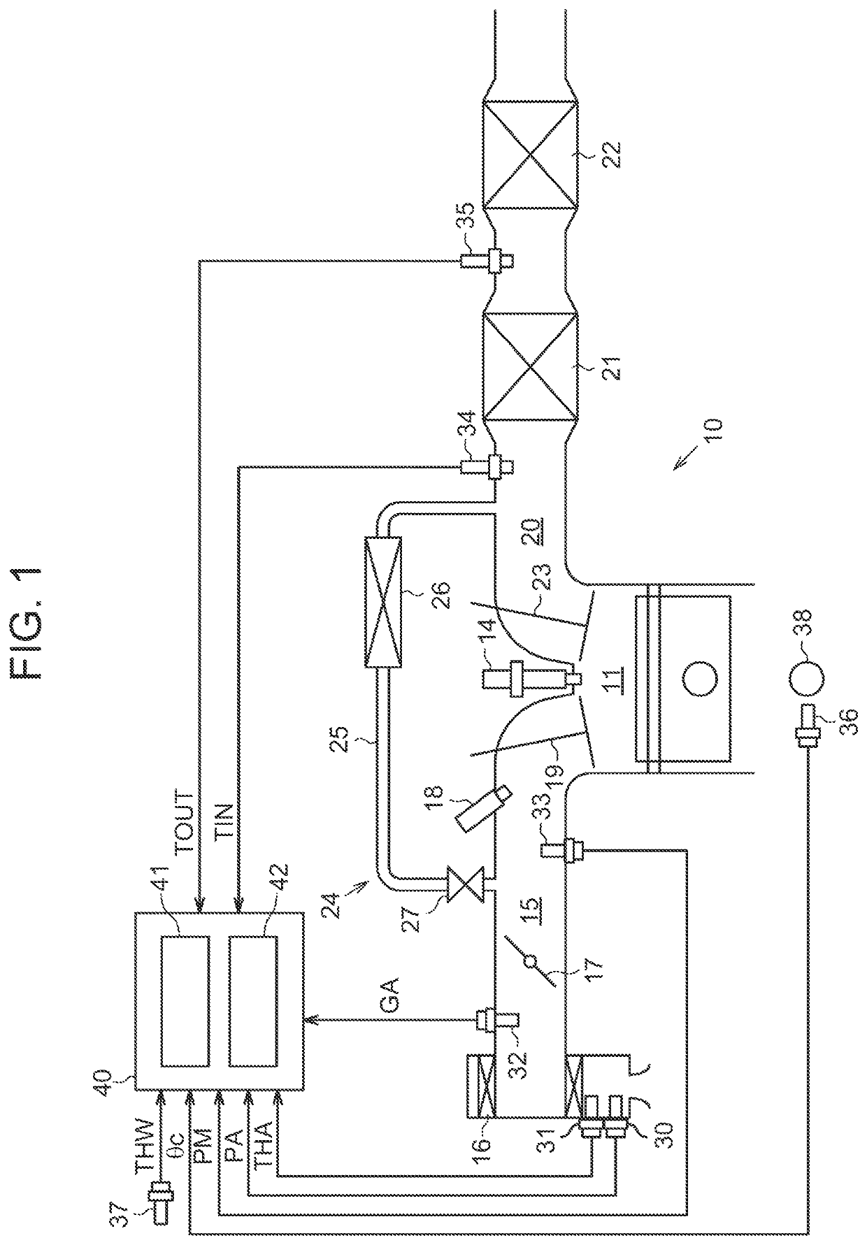
[0057]In the embodiment, the first diagnosis process for diagnosing whether the exhaust gas recirculation device 24 has an abnormality and the second diagnosis process for determining whether the exhaust gas cleaning filter 21 has a fracture are executed during fuel cut-off control. If these first diagnosis process and second diagnosis process are executed at the same time, the diagnostic accuracy of the second diagnosis process may decrease.

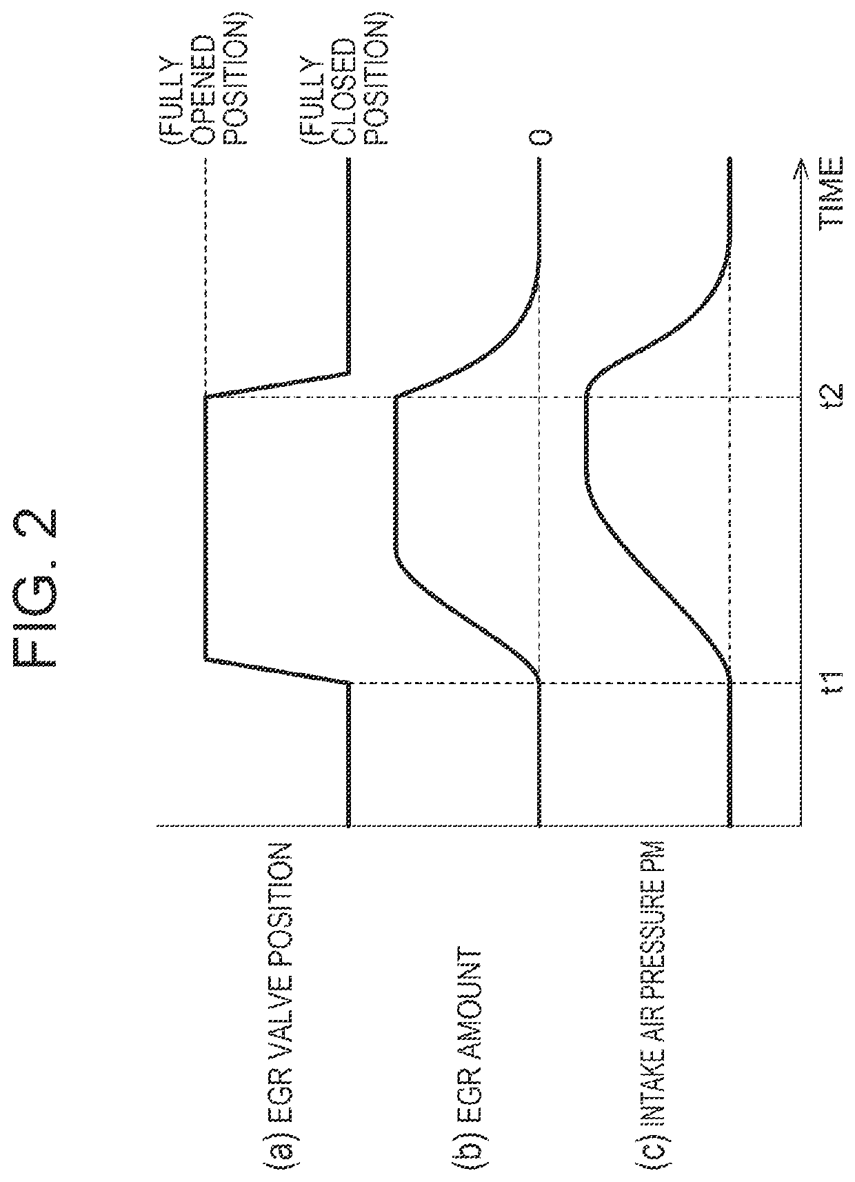
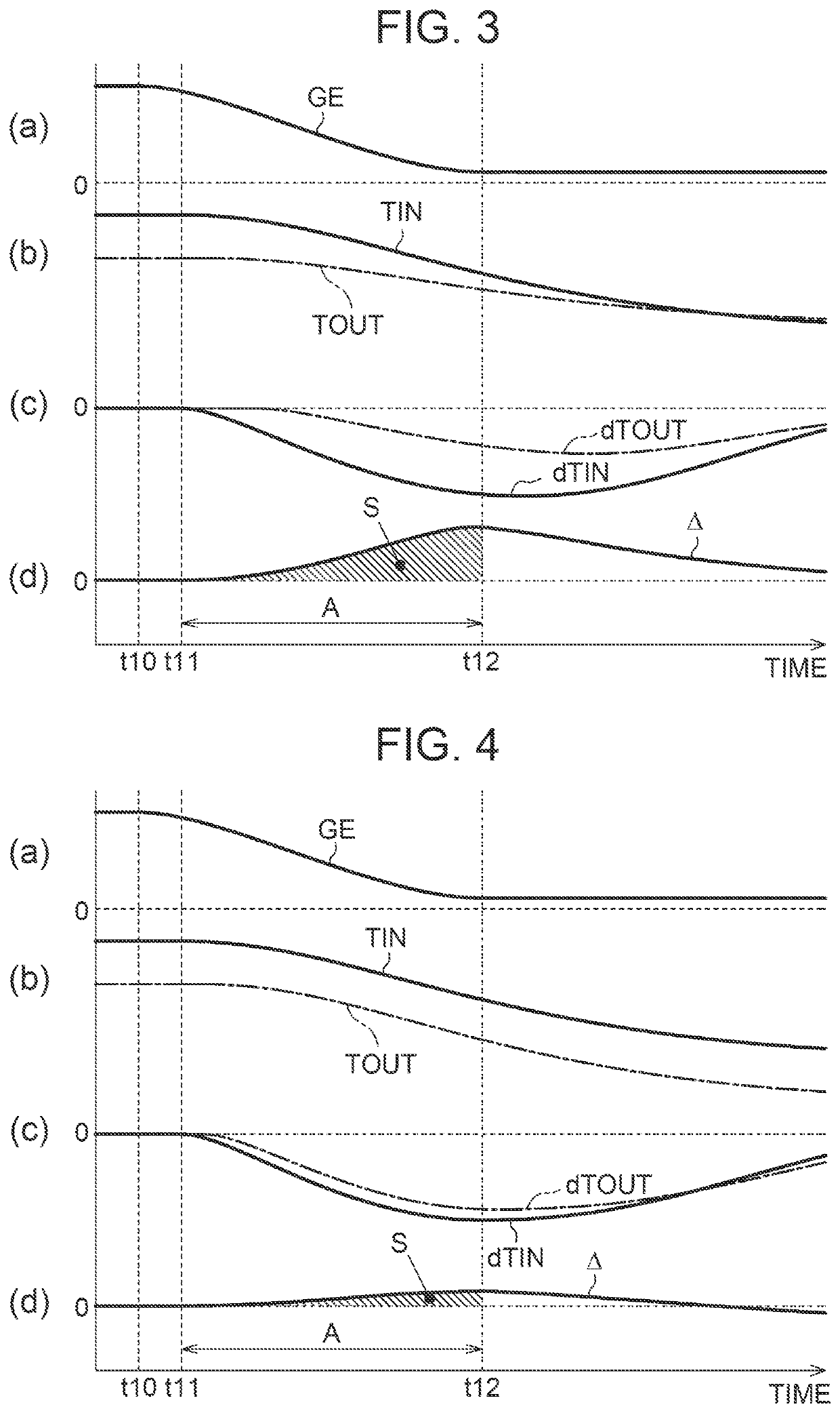
[0058]The reason is as follows: In the first diagnosis process, during fuel cut-off control, the EGR valve position is changed and whether the exhaust gas recirculation device 24 has an abnormality is diagnosed based on the amount of change that the intake air pressures PM undergoes as a result of the change. In the second diagnosis process, whether the exhaust gas cleaning filter 21 has a fracture is diagnosed based on measured values of the inc...


PUM


Abstract

Upon a predetermined first diagnosis execution condition being met, an electronic control unit executes a first diagnosis process of diagnosing whether an exhaust gas recirculation device has an abnormality based on an amount of change that a measured value of an intake air pressure undergoes as a result of a change in an EGR valve position. When a predetermined second diagnosis execution condition is met and, moreover, the first diagnosis process is not being executed, the electronic control unit executes a second diagnosis process of diagnosing whether an exhaust gas cleaning filter has a fracture based on measured values of an incoming gas temperature and an outgoing gas temperature.

Description

CROSS-REFERENCE TO RELATED APPLICATION[0001]This application claims priority to Japanese Patent Application No. 2021-001536 filed on Jan. 7, 2021, incorporated herein by reference in its entirety.BACKGROUND1. Technical Field[0002]The present disclosure relates to an engine control device configured to perform a failure diagnosis of an exhaust gas cleaning filter that collects fine particulate matter etc. in exhaust gas, and a failure diagnosis of an exhaust gas recirculation device that recirculates part of the exhaust gas back to an intake air passage.2. Description of Related Art[0003]Among devices applied to an engine, an exhaust gas recirculation (EGR) device recirculates part of exhaust gas back to an intake air passage. The EGR device includes an EGR passage connecting an exhaust gas passage and the intake air passage to each other, and an EGR valve installed in the EGR passage. The EGR valve changes a flow passage area of the exhaust gas recirculated back to the intake air pa...

Claims


Application Information

Patent Timeline
IPC IPC(8): F02M26/49F01N3/021F02M35/10F01N11/00
CPCF02M26/49F01N11/00F02M35/10373F01N3/021F01N2550/04Y02T10/40
Inventor SUGIMOTO, HITOKI
Owner TOYOTA JIDOSHA KK
Learn More