Optical coherence tomography apparatus, imaging method, and non-transitory computer readable medium storing imaging program

a coherence tomography and optical coherence technology, applied in the field of optical coherence tomography apparatus, imaging method, non-transitory computer readable medium storing imaging program, can solve the problems of reducing measurement accuracy, increasing the size and cost of the apparatus, and limiting the speed of increasing speed

Pending Publication Date: 2022-07-07
NEC CORP
View PDF4 Cites 0 Cited by
  • Summary
  • Abstract
  • Description
  • Claims
  • Application Information

AI Technical Summary

Benefits of technology

[0024]There are provided an optical coherence tomography apparatus, an imaging method, and a non-transitory computer readable medium storing

Problems solved by technology

Further, since an increase in scanning speed results in a decrease in measurement accuracy, there is a limitation in increasing the speed.
A method of using another sen

Method used


Image

  • Optical coherence tomography apparatus, imaging method, and non-transitory computer readable medium storing imaging program
  • Optical coherence tomography apparatus, imaging method, and non-transitory computer readable medium storing imaging program
  • Optical coherence tomography apparatus, imaging method, and non-transitory computer readable medium storing imaging program

Examples


first example embodiment

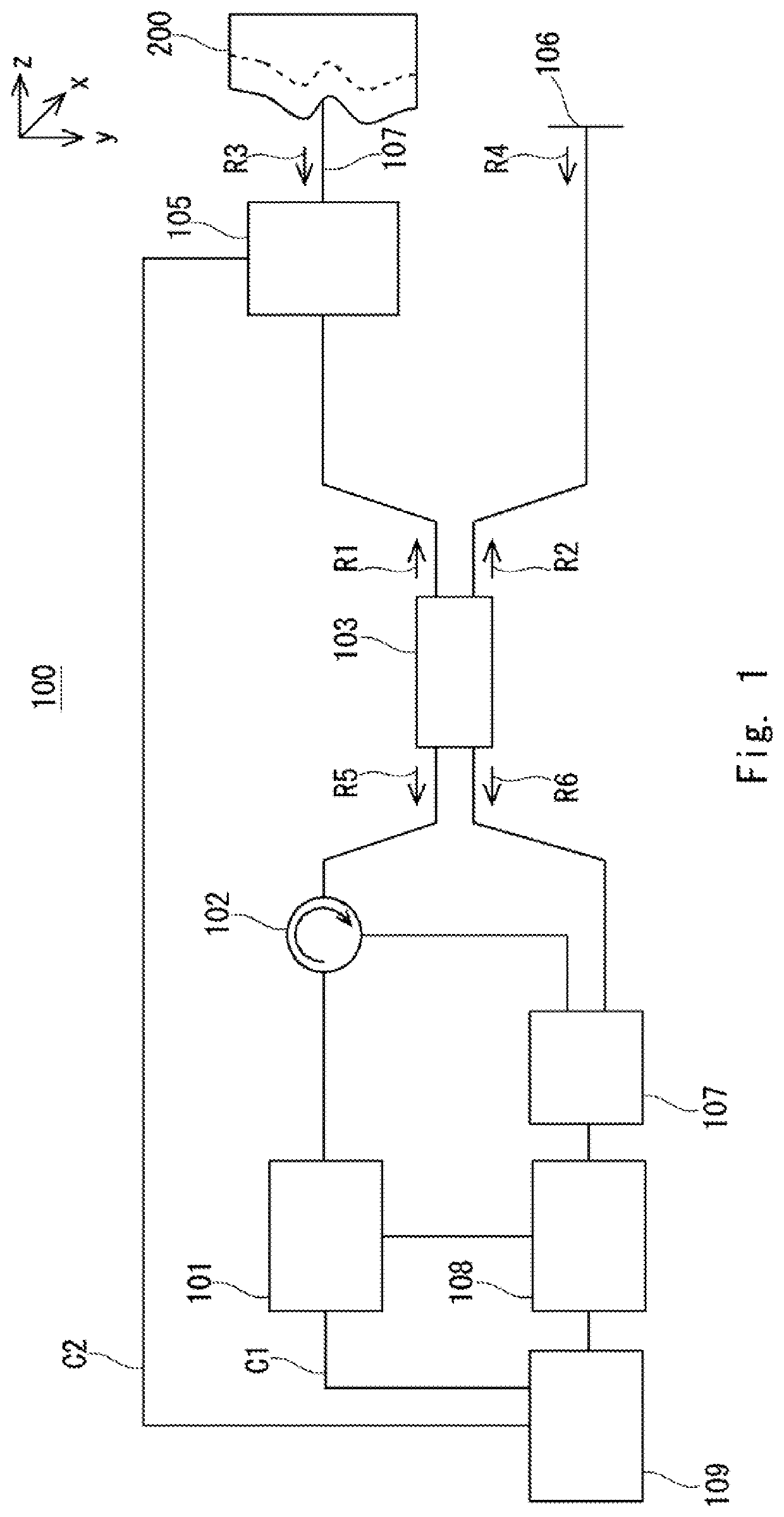
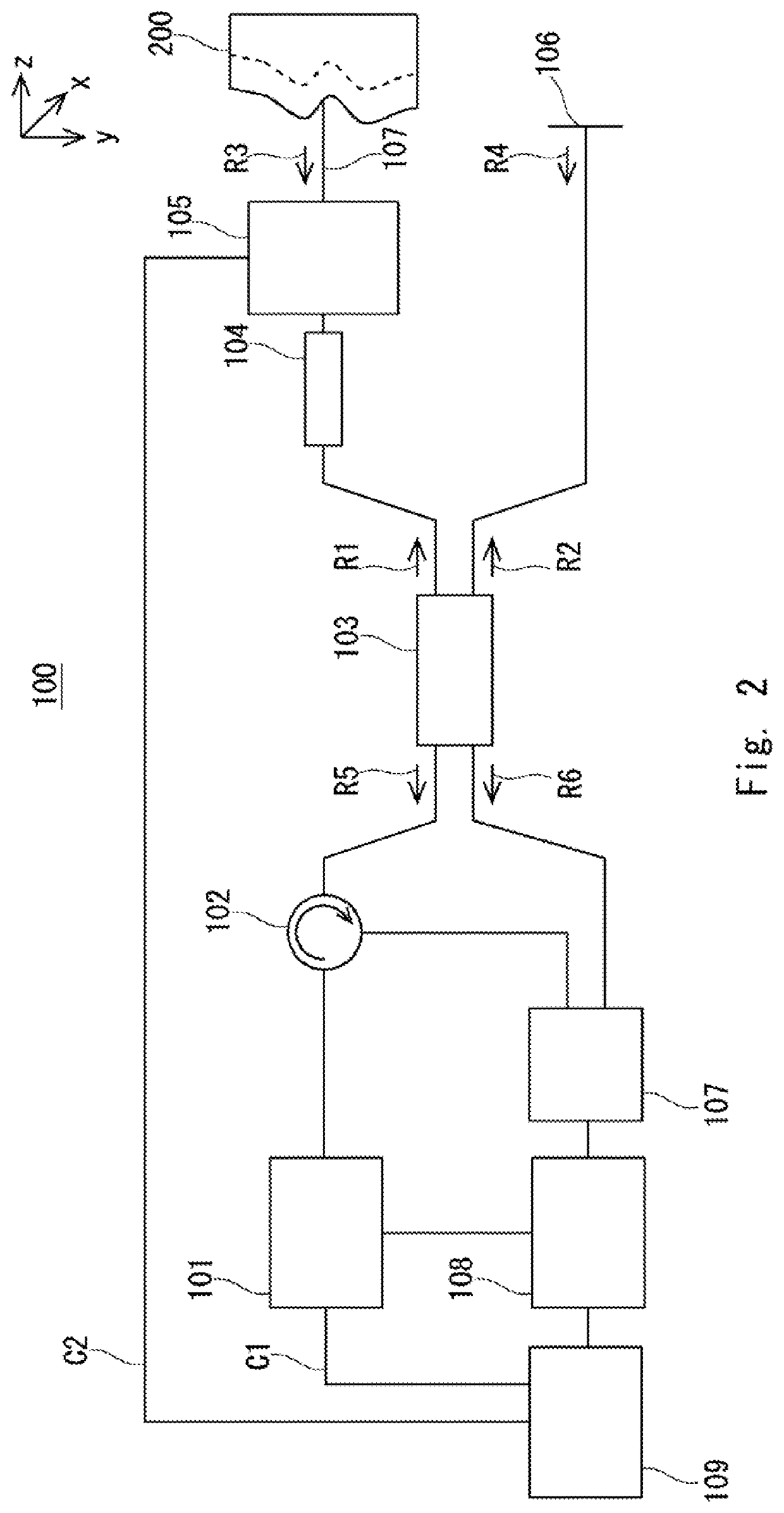
[0048]An optical coherence tomography apparatus 100 according to a first example embodiment of the present disclosure is described hereinafter. FIG. 2 is a view showing an example of the optical coherence tomography apparatus 100 according to the first example embodiment. As shown in FIG. 2, the optical coherence tomography apparatus 100 includes a wavelength sweeping laser light source 101, a circulator 102, a branching and merging device 103 serving as a branching unit and a merging unit, a fiber collimator 104, an irradiation optical system 105 serving as an irradiation unit, a reference light mirror 106, a balanced photodetector 107 serving as a measurement unit, an optical spectrum data generation unit 108 serving as a measurement unit, a control unit 109, and so on.

[0049]The wavelength sweeping laser light source 101 generates a wavelength-swept optical pulse according to a wavelength sweeping control signal C1 that is input from the control unit 109. To be specific, the wavel...


PUM


Abstract

An optical coherence tomography apparatus (100) includes a wavelength sweeping laser light source (101), a branching and merging device (103) that branches a light beam emitted from the wavelength sweeping laser light source (101) into an object light beam and a reference light beam, an optical spectrum data generation unit (108) that generates information about wavelength dependence of an intensity difference between a plurality of interference light beams generated by interference between an object light beam scattered from a measurement object (200) and a reference light beam, and a control unit (109) that acquires structural data of the measurement object (200) in a depth direction on the basis of the information about wavelength dependence, and connects a plurality of pieces of structural data in the depth direction acquired at different positions in a scanning direction of the measurement object (200), wherein preliminary measurement is performed by causing the wavelength sweeping laser light source (101) to emit a light beam swept in a wavelength sweep range narrower than a wavelength sweep range in actual measurement, and the actual measurement is performed when it is determined that the measurement object (200) is at a position suitable for performing the actual measurement on the basis of results of the preliminary measurement.

Description

TECHNICAL FIELD[0001]The present disclosure relates to an optical coherence tomography apparatus, an imaging method, and a non-transitory computer readable medium storing an imaging program.BACKGROUND ART[0002]As a technique for performing tomographic imaging in the vicinity of a surface of a measurement object, there is an Optical Coherence Tomography (OCT) technology. In the OCT technology, tomographic imaging of the vicinity of the surface of a measurement object is performed by utilizing interference between a scattered light beam (hereinafter also referred to as a “backscattered light beam”) from the inside of the measurement object and a reference light beam when the measurement object is irradiated with a light beam. Recently, applications of the OCT technology to medical diagnosis and industrial product inspection have expanded.[0003]In the OCT technology, a position of a part of the measurement object in an optical axis direction, which is a depth direction, where the objec...

Claims


Application Information

Patent Timeline
IPC IPC(8): G01B9/02091
CPCG01B9/02091A61B5/0066A61B3/10A61B1/00G01B9/02004G01B2290/65
Inventor SHIBAYAMA, ATSUFUMINAKAMURA, SHIGERU
Owner NEC CORP
Why Eureka
Try Eureka