
Flexible wiring member

Pending Publication Date: 2022-07-07
YAZAKI CORP
View PDF6 Cites 1 Cited by
  • Summary
  • Abstract
  • Description
  • Claims
  • Application Information

AI Technical Summary

Benefits of technology

The present invention aims to provide a flexible wiring member that can carry a large amount of current and easily be wired. The invention solves the problem of increased rigidity and reduced flexibility when using components with larger cross-sectional areas to flow a large current. The invention aims to allow for tolerance and workability in wiring, reducing the number of work steps and parts, lowering component costs, and improving work efficiency. The invention is designed to have high flexibility and easy wiring as its technical effect.

Problems solved by technology

Since bending is difficult when the rigidity is increased, it is difficult to absorb tolerance in a wiring member, and workability of wiring a wire harness in a vehicle is poor.
Further, even when the power supply line and the communication line are individually wired by independent components, the number of work steps increases.
In a case where components having different types of electric wires or different cross-sectional areas are selectively used for each path in accordance with a current value to be handled, since the number of parts of a cable increases, component costs may increase and work efficiency may be low.

Method used


Image

  • Flexible wiring member
  • Flexible wiring member
  • Flexible wiring member

Examples


Embodiment Construction

[0027]A specific embodiment of the present invention will be described below with reference to the drawings.

[0028]

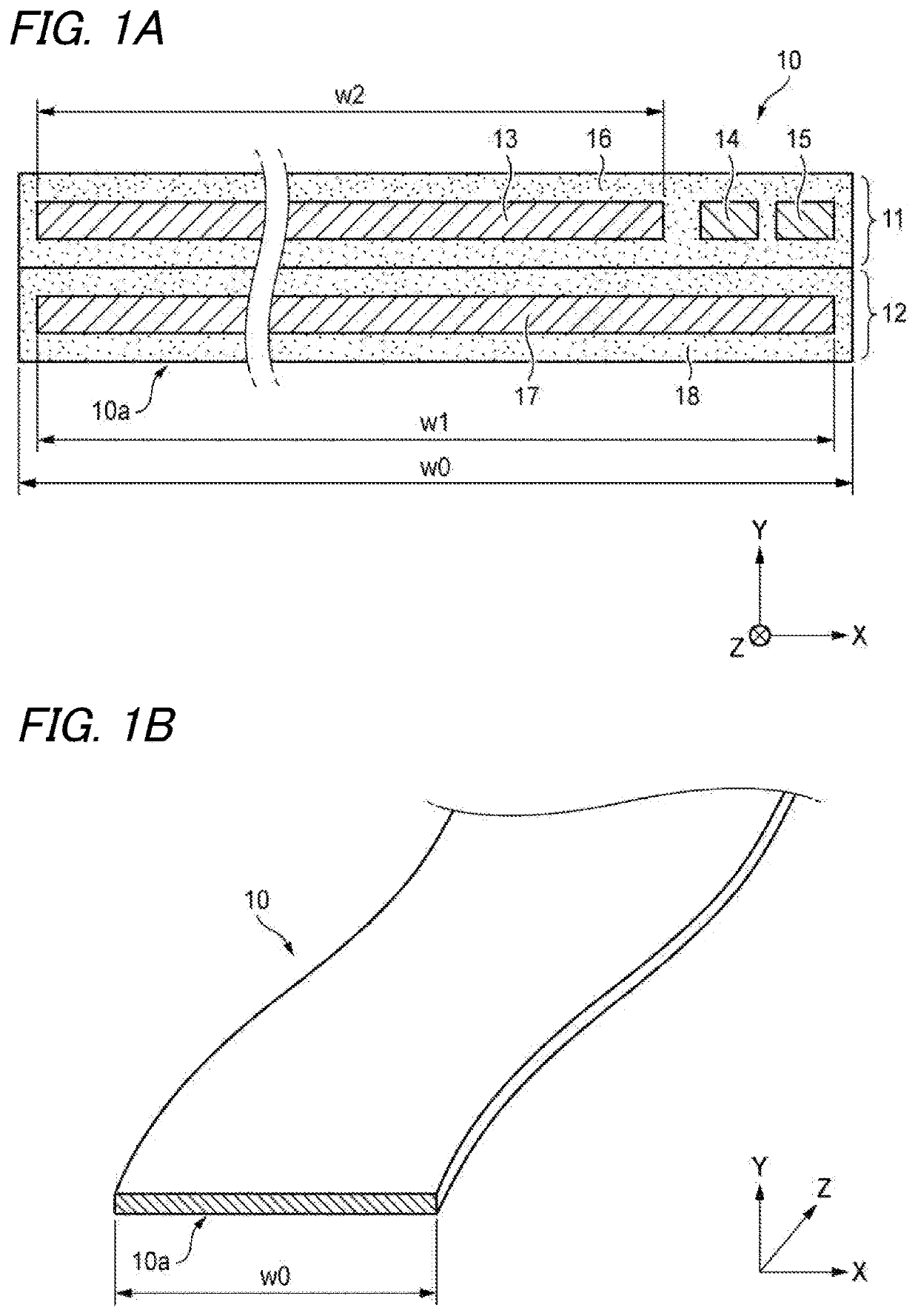
[0029]FIG. 1A is a longitudinal cross-sectional view and FIG. 1B is a perspective view both showing a flexible wiring member 10 according to an embodiment of the present invention.

[0030]In FIGS. 1A and 1B, an X axis, a Y axis, and a Z axis respectively correspond to a width direction, a thickness direction, and a length direction of the flexible wiring member 10.

[0031]As shown in FIGS. 1A and 1B, the flexible wiring member 10 has a structure suitable for mounting in a vehicle or the like and suitable for being used as a wiring member for a wire harness that electrically connects a plurality of electronic devices (ECU and the like) to one another. The flexible wiring member 10 can simultaneously connect both a power supply path and a communication path. In recent years, a vehicle such as a hybrid vehicle or an electric vehicle often handles a high-voltage power supply. Ac...


PUM


Abstract

There is provided a flexible wiring member capable of electrically connecting desired points separated in a length direction. The flexible wiring member includes conductor holding layers that are formed in a state of being stacked in a thickness direction and being electrically insulated from one another; power supply line conductors that have a wide width and are respectively disposed in both of a first conductor holding layer and a second conductor holding layer adjacent to each other in the thickness direction; and communication line conductors that have a width smaller than that of the power supply line conductors and are disposed in one of the first conductor holding layer and the second conductor holding layer, in which the conductor holding layers are formed by an insulating resin, and directly cover the power supply line conductors and the communication line conductors.

Description

CROSS REFERENCE TO RELATED APPLICATIONS[0001]This application is based on and claims priority from Japanese patent application No. 2021-000949 filed on Jan. 6, 2021, the entire contents of which are incorporated herein by reference.TECHNICAL FIELD[0002]The present invention relates to a flexible wiring member that can be used for electrically connecting a plurality of devices in a vehicle or the like.BACKGROUND ART[0003]In a vehicle, a plurality of devices such as electronic control units (ECU) are generally electrically connected to one another using a wiring member configured as a wire harness or the like. In such a case, the wiring member that connects the plurality of devices often includes a wiring member for a power supply line and a wiring member for a communication line. It is assumed that the wiring member for a power supply line and the wiring member for a communication line are wired in a manner of passing through almost the same paths, but these wiring members are normal...

Claims


Application Information

Patent Timeline
IPC IPC(8): H01B7/08H01B7/00
CPCH01B7/0823H01B7/0009H01B7/0208H01B7/04H01B9/003H01B11/00
Inventor TAKAMATSU, MASAHIROICHIKAWA, YOSHIAKI
Owner YAZAKI CORP
Learn More