Patch-type drug infusion device

a drug infusion device and patch-type technology, applied in the field of patch-type drug infusion devices, can solve the problems of poor user experience, large size of existing drug infusion devices, easy to be caught, etc., and achieve the effects of reducing the volume of the infusion device, reducing production costs, and simplifying the design, manufacturing and position detection of the piston

Pending Publication Date: 2022-07-14
MEDTRUM TECH
View PDF0 Cites 0 Cited by
  • Summary
  • Abstract
  • Description
  • Claims
  • Application Information

AI Technical Summary

Benefits of technology

[0005]The embodiment of this invention discloses a patch-type drug infusion device. By adjusting the internal structure and layout of the infusion device, the volume of the infusion device and the production cost are both reduced.
[0013]Compared with the prior art, the technical solution of the present invention has the following advantages:
[0014]In the patch-type drug infusion device disclosed in the present invention, the driving unit includes one driving portion, and the driving unit rotates to drive the driving portion to push the wheel teeth to rotate the driving wheel. Disposing one driving portion on the driving unit reduces the overall width of the driving unit and the driving unit's rotation amplitude, so that the internal structure of the infusion device will be more compact, leading to reduced volume of the infusion device and lower production cost. Secondly, the rigid screw moves in a linear non-rotating manner, which simplifies the design, manufacturing and position detection of the piston and reduces design and production costs.
[0015]Furthermore, the direction in which the power unit applies a force to the driving unit is parallel to the forward direction of the rigid screw. Such a design can make full use of the internal structural layout of the infusion device, reduce the space required for mechanical operation of the power unit, and thereby reduce the volume of the infusion device.
[0016]Furthermore, the infusion device includes two driving units and one driving wheel, the two driving units are coaxial, or the two driving units are respectively disposed on the two sides of the driving wheel. The two driving units and one driving wheel cooperate with each other, which reduces the rotation amplitude of the driving unit, making the internal structure of the infusion device more compact, and further reducing the volume of the infusion device. At the same time, the two driving units cooperating with each other can improve the infusion accuracy of the device, so that the amount of infused drugs can be controlled precisely.

Problems solved by technology

At present, the existing drug infusion devices are relatively large in size, and are prone to be caught by clothes after sticking to the skin.
So the user experience is poor.
At the same time, the internal structure is complex, with higher design and production costs.
Therefore, the prior art desperately needs a drug infusion device with smaller size and lower cost.

Method used


Image

  • Patch-type drug infusion device
  • Patch-type drug infusion device
  • Patch-type drug infusion device

Examples


first embodiment

The First Embodiment

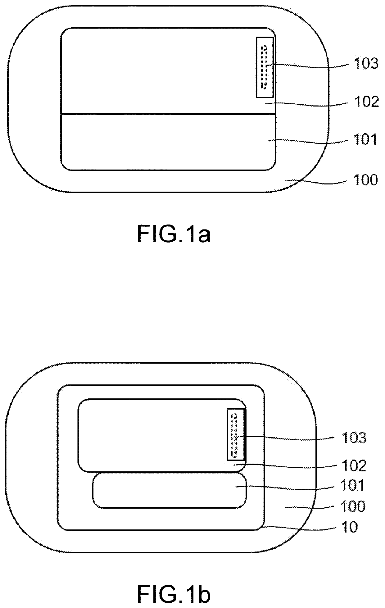
[0033]FIG. 1a and FIG. 1b are schematic top structural diagrams of a patch-type drug infusion device according to one embodiment of the present invention.

[0034]The patch-type drug infusion device includes an adhesive patch 100, program unit 101, infusion unit 102 and infusion needle 103.

[0035]The program unit 101 is used for controlling drug infusion, controlling power output of the power unit, receiving signals from position detector(s), establishing wireless communication with remote devices, and the like.

[0036]The infusion unit 102 includes various units for realizing the mechanical function for drug infusion, which will be described in detail below.

[0037]In the embodiment of the present invention, the program unit 101 and the infusion unit 102 are designed separately and connected by a waterproof plug. The program unit 101 can be reused, while the infusion unit 102 can be discarded after a single use. In another embodiment of the present invention, the infusi...

second embodiment

The Second Embodiment

[0061]FIG. 6a-FIG. 6b are schematic structural diagrams of the driving portion 251 pushing the wheel teeth 241 to move according to the second embodiment of the present invention. The difference between the second embodiment and the first embodiment is that the direction of the power unit pulling force FP is perpendicular to the forward direction DA of the rigid screw 230 (in the second embodiment), and other structural designs are the same as those in the first embodiment.

[0062]FIG. 6a is a view along the axial direction of the rigid screw 230, and FIG. 6b is a schematic plan view of the structure of FIG. 6a. The rotating shaft 260 and the rebound unit 270 are provided on the base (not shown). As described above, the driving unit 250 rotating reciprocally in the R direction drives the driving portion 251 to push the wheel teeth 241, causing the driving wheel 240 to rotate in the W direction, and to drive the rigid screw 230 to advance in the DA direction. The d...

third embodiment

The Third Embodiment

[0065]FIG. 8 is a schematic structural diagram of the driving portion 351a or 351b pushing the wheel teeth 341 to move according to the third embodiment of the present invention. The difference from the previous embodiment is that two driving units 350a and 350b are provided which can rotate coaxially The driving unit 350a rotates reciprocally in the R direction around the rotating shaft 360 under the action of the power unit 380a and the rebound unit 370a. Similarly, the driving unit 350b rotates reciprocally in the R direction around the rotating shaft 360 under the action of the power unit 380b and the rebound unit 370b. In the embodiment of the present invention, the rotations of the two driving units do not interfere with each other.

[0066]Preferably, in the embodiment of the present invention, the driving unit 350a and the driving unit 350b rotate asynchronously. That is, when the driving portion 351a of the driving unit 350a pushes the wheel teeth 341 to mo...


PUM


Abstract

A patch-type drug infusion device includes an infusion unit. The infusion unit includes a drug storage unit, a piston, a rigid screw, a rotating shaft, a rotatable driving unit, a driving wheel provided with wheel teeth, a power unit and a rebound unit. The driving unit can rotate around the rotating shaft, driving the driving portion of the driving unit to push the wheel teeth to rotate the driving wheel which engages the rigid screw to move forward in a non-rotating way. The device also includes position detectors, a program unit, an infusion needle and an adhesive patch. The program unit is connected to the infusion unit to control drug infusion and convert received electrical or magnetic signals into the piston position information.

Description

TECHNICAL FIELD[0001]The present invention mainly relates to the field of medical instruments, in particular to a patch-type drug infusion device.BACKGROUND[0002]A drug infusion device can continuously deliver drug into a patient's body for disease treatment. Drug infusion devices are widely used in the field of diabetes treatment, which continuously infuse required dosage of insulin into the patient's subcutaneous tissue, thereby simulating the secretion function of the pancreas to keep the blood glucose stable. The drug fluid is usually stored inside the infusion pump. The existing drug infusion device, controlled by remote device, is usually attached directly on the patient's skin through a medical adhesive tape.[0003]At present, the existing drug infusion devices are relatively large in size, and are prone to be caught by clothes after sticking to the skin. So the user experience is poor. At the same time, the internal structure is complex, with higher design and production cost...

Claims


Application Information

Patent Timeline
Patent Type & Authority Applications(United States)
IPC IPC(8): A61M5/142A61M5/315A61M5/145G16H20/17
CPCA61M5/14248A61M5/14216A61M5/31583A61M2230/201G16H20/17A61M2005/14208A61M2005/14252A61M5/1452A61B5/14503A61B5/14532A61M2205/33A61M2230/63A61M2230/005A61M5/16831A61M2205/0272A61M5/1723A61M5/14244A61M5/16804G16H40/67A61M2205/3317A61M2205/3576A61M2205/50A61M5/14236A61M5/1454A61M5/16877A61M2005/14506A61M2205/0233A61M2205/3327
Inventor YANG, CUIJUN
Owner MEDTRUM TECH
Why Eureka
Try Eureka