Eureka AIR delivers breakthrough ideas for toughest innovation challenges, trusted by R&D personnel around the world.

Method for decoding a luminous communication signal and optoelectronic system

Pending Publication Date: 2022-07-14
ELLIPZ SMART SOLUTIONS EUROPE
View PDF0 Cites 0 Cited by
  • Summary
  • Abstract
  • Description
  • Claims
  • Application Information

AI Technical Summary

Benefits of technology

The decoding method described in this patent makes it possible to better detect and decode the logic values of digital data transmitted by light. This is useful for optimizing the transmission of digital data using light, and also makes it compatible with the use of a camera in a mobile phone. The method uses an emitting system to generate a light communication signal with two different frequencies of oscillation, representing different logic values of the digital data. The second frequency is chosen to ensure reliability and robustness of the light communication system. The technical effect is improved data transmission using light.

Problems solved by technology

Light communication systems of this kind are costly to develop and integrate because it is necessary both to deploy a network of lighting devices and to make a specific terminal available to its users.
However, due to the bandwidth of such a camera, only low data rates make its use compatible with communication by light.
In addition, the prototypes currently developed are still unreliable and do not make it possible to receive a constant flow of data without losses.

Method used


Image

  • Method for decoding a luminous communication signal and optoelectronic system
  • Method for decoding a luminous communication signal and optoelectronic system
  • Method for decoding a luminous communication signal and optoelectronic system

Examples


Embodiment Construction

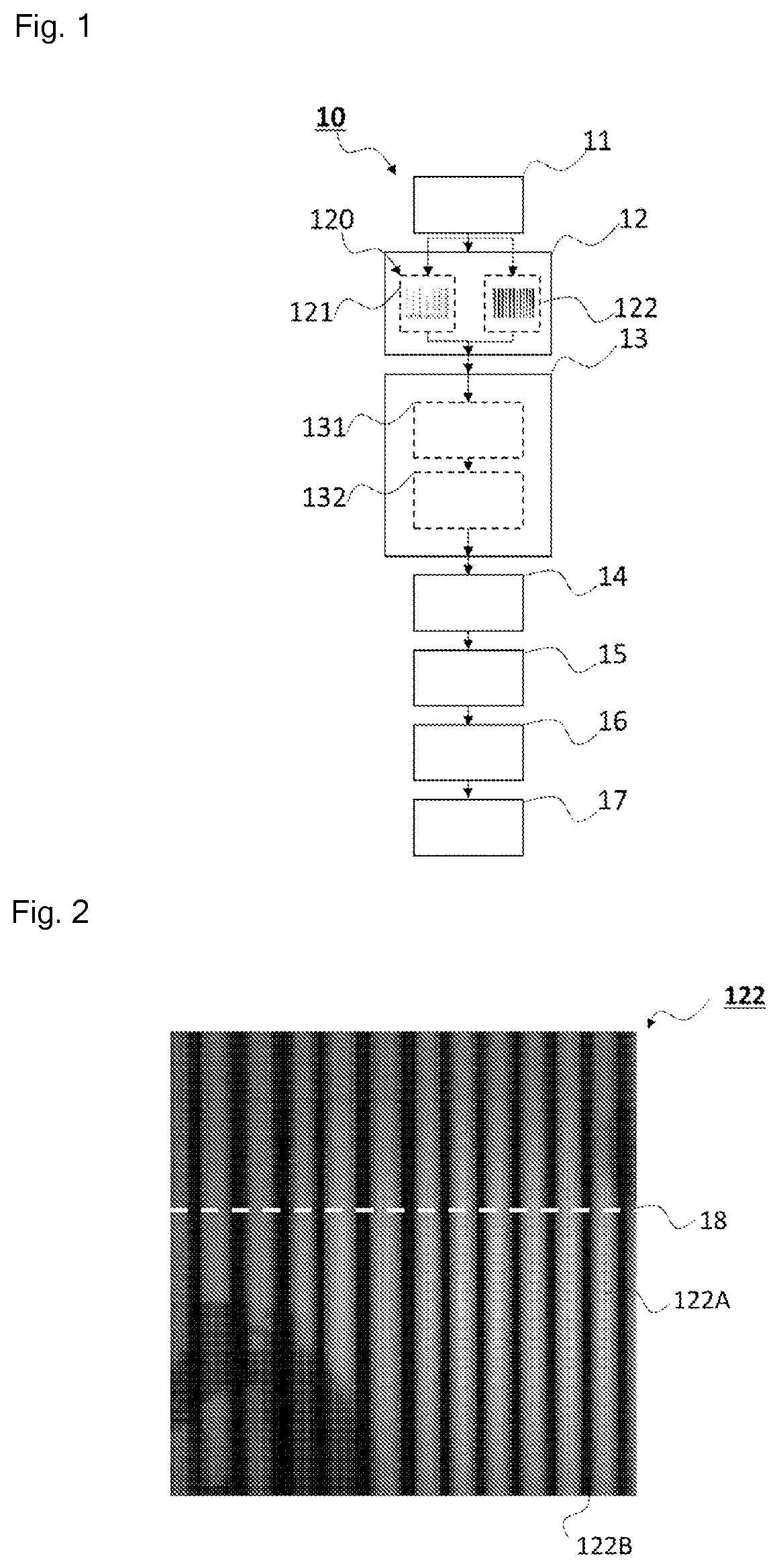
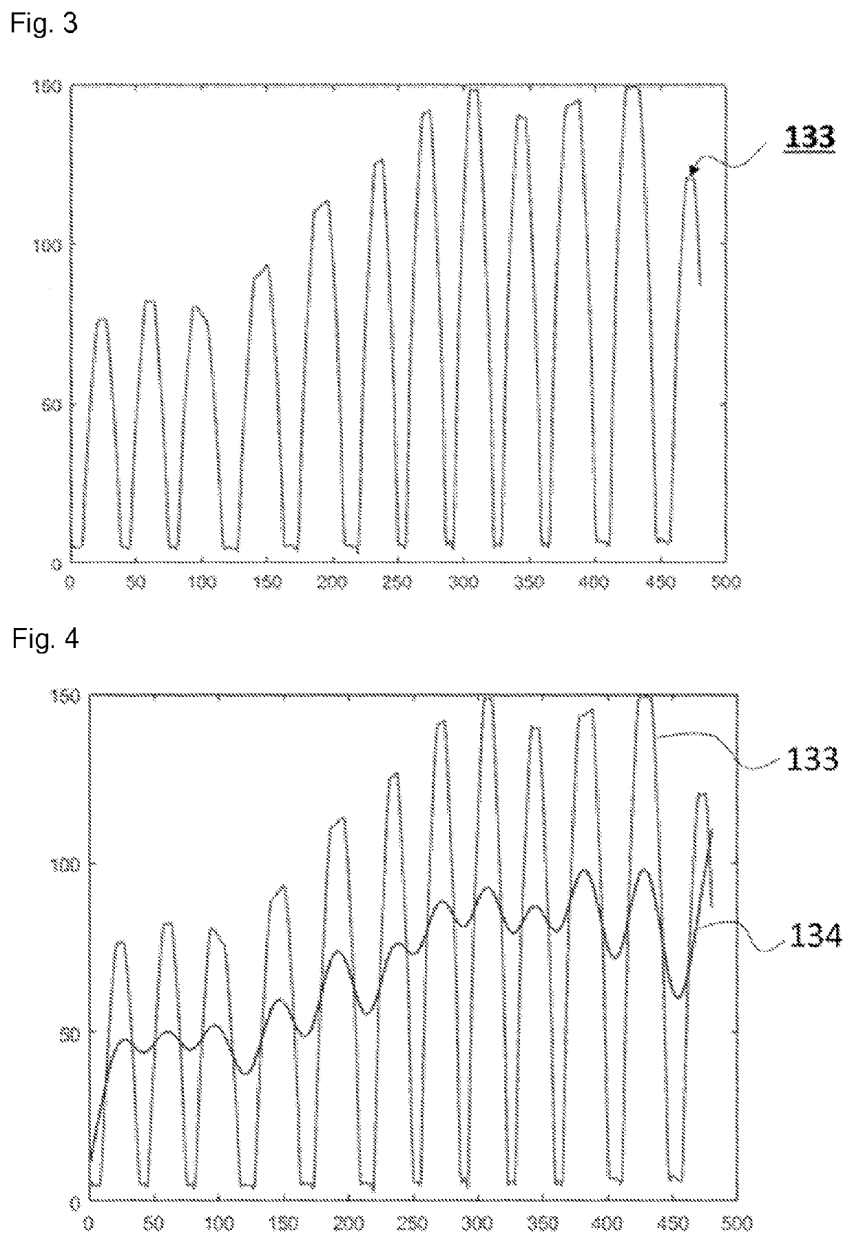
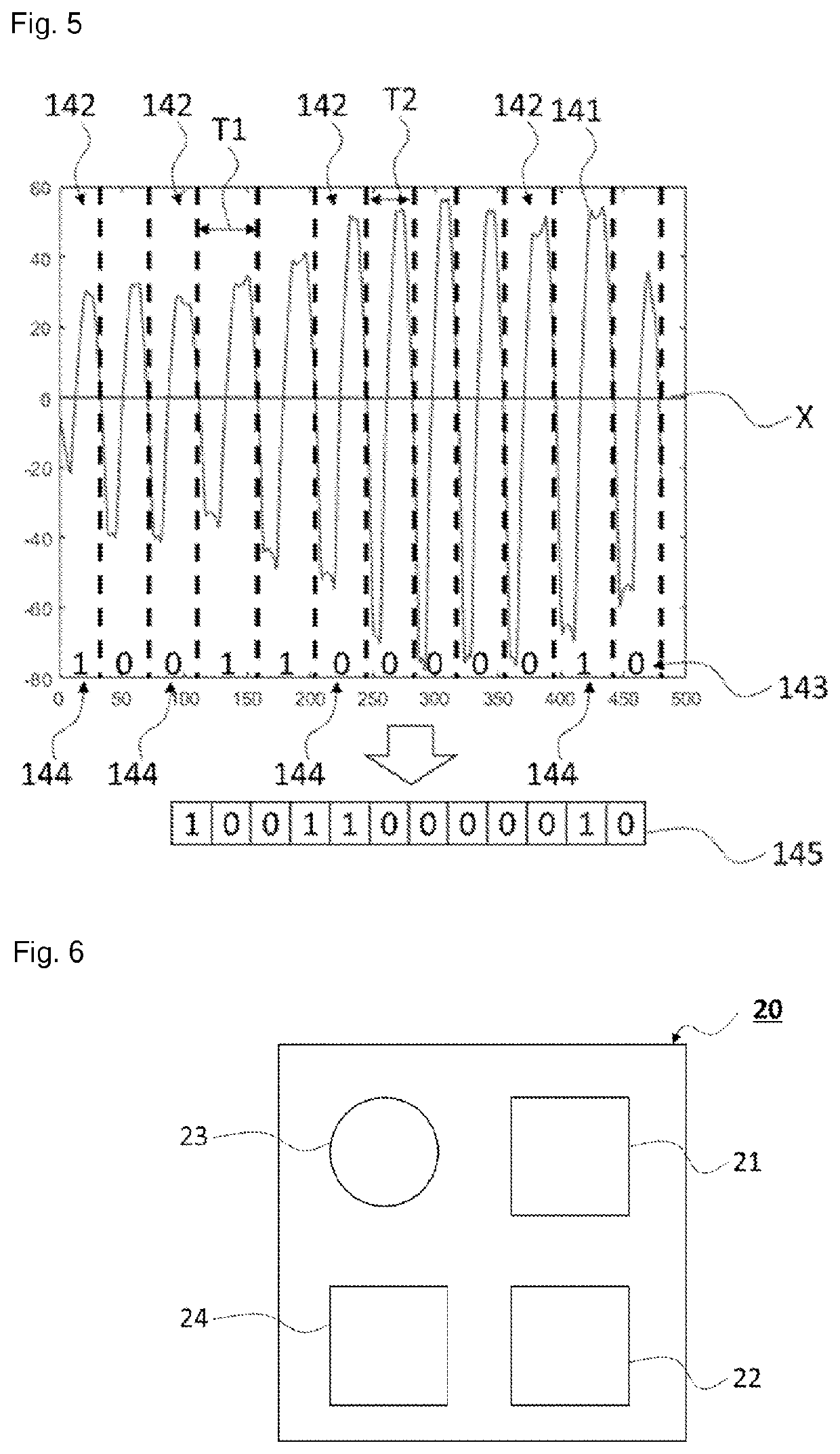
[0048]With reference to FIGS. 1 to 5, an embodiment of the decoding method 10 according to the first aspect of the invention is described below, the decoding method 10 comprising one or more iterations of the following steps:[0049]a step of acquiring 11 the modulated light signal with an areal photodetector;[0050]a step of converting 12 the light signal detected by the areal photodetector into a two-dimensional representation 122 representing a variation in light intensity of said light signal detected on the surface of said areal photodetector, the step of converting being carried out by an analog-digital converter;[0051]a step of computing 13 a trend function using all or some of the two-dimensional representation 122, the step of computing being carried out by a computing unit;[0052]a step of subtracting 14 the trend function from the two-dimensional representation 122 in order to obtain a processed signal from the light signal detected by the areal photodetector, the step of sub...


PUM


Abstract

The invention relates to a method for decoding (10) a modulated light signal (35) carrying a digital data set, the decoding method (10) comprising a step of searching (12, 13, 14, 15) for at least two frequencies of oscillation of a digital transcription of the light signal detected by a photodetector (23), each frequency of oscillation being representative of a logic value of the bits constituting the digital data carried by the light signal. Advantageously, a most significant bit is represented by a first frequency of oscillation and a least significant bit is represented by a second frequency of oscillation, the first frequency of oscillation being chosen so as to form, at the photodetector (23), a digital signal that is larger than that formed by the second frequency of oscillation by at least 4 elementary detection units of said photodetector (23).The invention also relates to an optoelectronic system (20) that implements a decoding method (10) of this kind.

Description

TECHNICAL FIELD[0001]The technical context of the present invention is that of communication by way of light in order to transport digital data by means of a modulated light beam. More specifically, the invention relates to a method for decoding a modulated light signal carrying a digital data set. The invention also relates to an optoelectronic system that makes it possible to implement a decoding method of this kind.PRIOR ART[0002]In the prior art, light communication systems are known, such as those which implement LiFi (“Light Fidelity”) technology, which allows digital data to be transmitted wirelessly by modulating the light emitted by LED (Light Emitting Diode) lights. LiFi technology is described in particular in the international standard IEEE802.15.[0003]A known use of this technology is linked to the development of indoor geolocation services in order to be able to locate a LiFi receiver in a network of LiFi transmitters formed by the same number of LED lighting devices. ...

Claims


Application Information

Patent Timeline
IPC IPC(8): H04B10/116H04B10/69H04B10/556
CPCH04B10/116H04B10/5563H04B10/691
Inventor TOPSU, SUATAARON, PEREZ OLIVAS HUETZINEMIR, GREEN OJEDA JACOBSEILLIERE, JEAN-BAPTISTEROOYMANS, JOHANNES OTTO
Owner ELLIPZ SMART SOLUTIONS EUROPE
Why Eureka
Eureka Blog
Learn More