Energy harvesting device

a technology of energy harvesting and solar energy, which is applied in the direction of wind motors with solar radiation, machines/engines, lighting and heating apparatus, etc., can solve the problems of high cost of pv and shw panels, insufficient roof space per living unit, and inability to meet building energy demand

Pending Publication Date: 2022-07-21
LEUNG CHI LAM
View PDF3 Cites 0 Cited by
  • Summary
  • Abstract
  • Description
  • Claims
  • Application Information

AI Technical Summary

Problems solved by technology

However, as buildings are becoming taller, the available roof space per living unit is no longer adequate to meet the energy demand of buildings.
While PV or solar hot water (SHW) panels can be directly integrated into building façades, such strategies rem

Method used


Image

  • Energy harvesting device
  • Energy harvesting device

Examples


Embodiment Construction

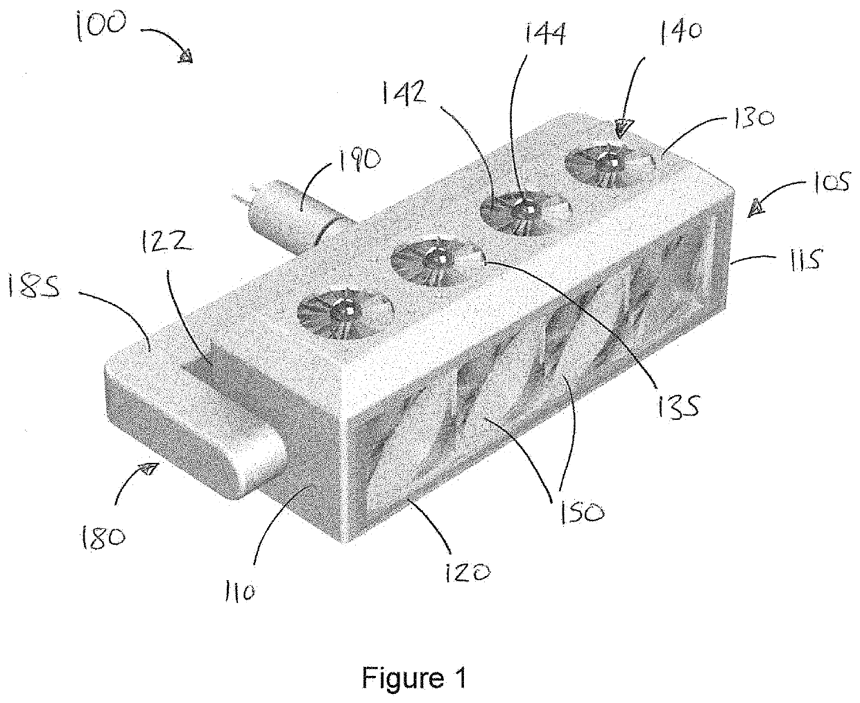
[0034]Referring to FIG. 1, an energy harvesting device 100 according to an embodiment of the invention comprises an elongate trough 105 attached to a mount 180.

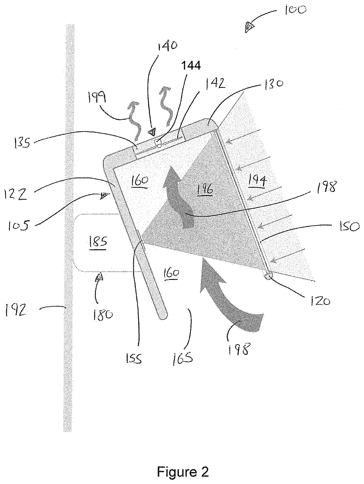
[0035]The mount comprises an arm portion 185 which is attached to opposing first and second end walls 110, 115 of the trough 105. The arm portion 185 is attached an actuator 190 which can rotate the arm portion 185 clockwise or anticlockwise about its axis. The actuator 190 may suitably be attached to the façade of a building (not shown). The arm portion 185 can rotate the trough 105 about its longitudinal axis.

[0036]As will be discussed in more detail below, the trough 105 comprises a first side 120, a second side 122, and a base portion 130. The ends of the first and second sides 120, 122 are capped by first and second end walls 110, 115. The base portion 130 has four apertures 135, inside each of which sits a vertical axis wind turbine 140. Each wind turbine 140 has a set of blades 142 attached to a rotor shaft 144. The fi...


PUM


Abstract

In general terms the present invention proposes a device 100 for harvesting renewable energy. The device 100 comprises a wind turbine 140, a channel 160 for directing wind 198 to the wind turbine 140, and a solar receiver 155 positioned on an internal of the channel 160 for receiving sunlight 194 entering the channel 160.

Description

TECHNICAL FIELD[0001]This invention relates to the utilisation of renewable resources to generate energy. In particular, though not exclusively, this invention relates to a device for harvesting renewable energy, a building having the device installed thereon, and a method of enhancing the efficiency of a wind turbine.BACKGROUND[0002]Global concern about electrical consumption and environmental sustainability has prompted the application of renewable energy sources in buildings. As the world population, at large, continues to migrate to cities, buildings are being built to increasing heights. In high-rise buildings, rooftops are typically used to install photovoltaic (PV) systems. However, as buildings are becoming taller, the available roof space per living unit is no longer adequate to meet the energy demand of buildings.[0003]While PV or solar hot water (SHW) panels can be directly integrated into building façades, such strategies remain relatively unpopular, due to the lower sol...

Claims


Application Information

Patent Timeline
IPC IPC(8): F03D9/00F03D80/60
CPCF03D9/007F03D80/60F03D9/37F05B2260/24F03D13/20Y02E10/46Y02E10/72Y02E10/728F03G6/045F24S90/00F05B2240/131F03D1/04
Inventor LEUNG, CHI LAM
Owner LEUNG CHI LAM
Why Eureka
Try Eureka