Piercing electrical connector

Pending Publication Date: 2022-07-21
DONGGUAN HONGRU CONNECTORS
View PDF0 Cites 0 Cited by
  • Summary
  • Abstract
  • Description
  • Claims
  • Application Information

AI Technical Summary

Problems solved by technology

Nevertheless, structural design of the connectors of the existing art is not reasonable.
As such, packaging costs of the connecto

Method used


Image

  • Piercing electrical connector
  • Piercing electrical connector
  • Piercing electrical connector

Examples


first embodiment

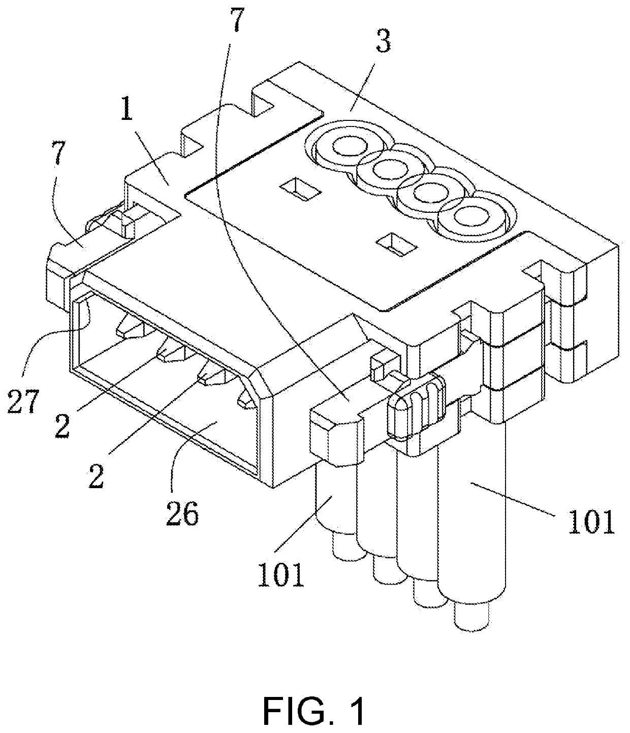
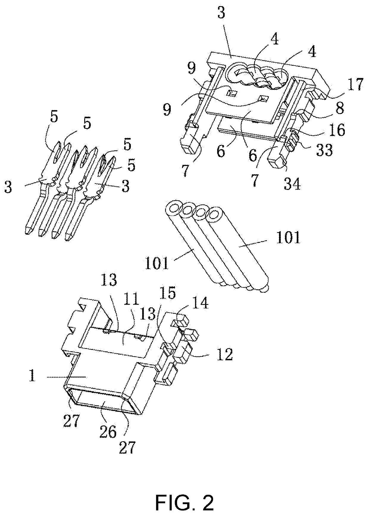
[0043]With reference to FIG. 1 to FIG. 5, a piercing electrical connector provided by the disclosure includes a wire end connector. The wire end connector has a wire end body 1, a wire end terminal 2 disposed on the wire end body 1, a wire cover 3 engaged and matched with the wire end body 1. The wire end body 1 and the wire cover 3 are both made of insulating plastic materials, for example, the wire end body 1 and the wire cover 3 are both formed by injection molding of injection molds. The wire cover 3 has wire accommodation holes 4 configured to accommodate external cable wires 101, and the cable wires 101 may be inserting flat wires or scattered wires. For instance, the cable wires 101 may be the common wire numbers, such as AWG22, AWG24, or AWG26 and the like, and a hole diameter of the wire accommodation holes 4 may be adjusted according to different wire numbers. Preferably, the wire accommodation holes 4 penetrate the wire cover 3, and in this way, after the cable wires 101 ...

second embodiment

[0081]With reference to FIG. 9, in this embodiment, the plate end connector is installed in a horizontal manner. The plate end connector includes an insulating body 45, conductive terminals 46 installed on the insulating body 45, and two reinforcement soldering sheets 47 installed at left and right sides of the insulating body 45. A structure of the insulating body 45 is substantially similar to the structure of the plate end body 28, and a structure of the conductive terminals 46 is substantially similar to the structure of the plate end terminals 29, so description thereof is not repeated herein. The structure of the reinforcement soldering foot 41 is identical to a structure of the reinforcement soldering sheets 47.

[0082]The insulating body 45 has a tongue plate 48. The tongue plate 48 protrudes from a middle portion of a front end surface of the insulating body 45, and the tongue plate 48 is parallel to the external circuit board 102. The conductive terminals 46 have soldering p...


PUM


Abstract

A piercing electrical connector includes a wire end connector. The wire end connector has a wire end body, a wire end terminal, and a wire cover engaged with the wire end body. The wire cover has a wire holding hole, and the wire end terminal has a piercing portion. The wire cover further has a clasping plate, a clasping arm and a first clasping head. The wire end body has a clasping groove, a clasping hole, a protrusion located in the clasping groove, a pre-locking groove and a locking groove that communicate with the clasping hole. When the wire end connector needs to be transported, the first clasping head extends into the pre-locking groove, and the protrusion abuts against a free end of the clasping plate so that the wire cover and the wire end body are pre-assembled together, and the piercing portion does not pierce a cable wire.

Description

TECHNICAL FIELD[0001]The disclosure relates to an electrical connector technology field. In particular, the disclosure discloses a piercing electrical connector.DESCRIPTION OF RELATED ART[0002]To facilitate ease of electrical connection of cable wires, in a connector of the existing art, a piercing terminal is used to pierce a cable wire, so as to accomplish the technique of rapid electrical connection. Nevertheless, structural design of the connectors of the existing art is not reasonable. In the existing art, a connector is required to be packaged in a tray, so that a cover shell and a plastic shell are prevented from being tightly assembled owing to collisions among connectors, which may cause the connectors from being plugged into cable wires normally. As such, packaging costs of the connectors are raised significantly.[0003]Moreover, when an existing connector is connected to a cable wire, a crimped external wire is required to be manually assembled into the plastic shell body....

Claims


Application Information

Patent Timeline
IPC IPC(8): H01R4/2406H01R13/627H01R13/506
CPCH01R4/2406H01R13/506H01R13/6272H01R4/2404H01R13/639H01R13/629H01R4/242H01R12/67
Inventor ZHU, FENG
Owner DONGGUAN HONGRU CONNECTORS
Why Eureka
Try Eureka