Diaphragm structure

a diaphragm and structure technology, applied in the direction of transducer diaphragms, electromechanical transducers, instruments, etc., can solve the problems of affecting the sound performance of the corresponding frequency band, unable to meet the different rigidity requirements of each part of the diaphragm at the same time, etc., to reduce the generation of troughs, improve the structural rigidity of the central part, and improve the effect of the structural rigidity

Pending Publication Date: 2022-07-28
MERRY ELECTRONICS (SHENZHEN) CO LTD
View PDF6 Cites 0 Cited by
  • Summary
  • Abstract
  • Description
  • Claims
  • Application Information

AI Technical Summary

Benefits of technology

[0004]The disclosure provides a diaphragm structure, the central part of which has better structural rigidity.
[0012]Based on the above, in the diaphragm structure of the disclosure, a structural strengthening part is formed at the top end of the central part, thereby increasing the structural rigidity of the central part. Accordingly, compared with conventional diaphragms, unexpected distortion during vibration is less likely to occur to the central part of the diaphragm structure of the disclosure, which can make the frequency response curve flatter and reduce the generation of troughs, thereby improving the sound output quality.

Problems solved by technology

However, nowadays, most diaphragms are made of a single material, which makes it difficult to meet the different rigidity requirements of each part of the diaphragm at the same time.
For example, the central part of the diaphragm, or dome, is prone to distortion due to insufficient rigidity, resulting in uneven vibration, and thus the sound performance of the corresponding frequency band is affected.

Method used


Image

  • Diaphragm structure
  • Diaphragm structure
  • Diaphragm structure

Examples


Embodiment Construction

[0017]Reference will now be made in detail to the exemplary embodiments of the disclosure, examples of which are illustrated in the accompanying drawings. Wherever possible, the same reference numbers are used in the drawings and the description to refer to the same or like parts.

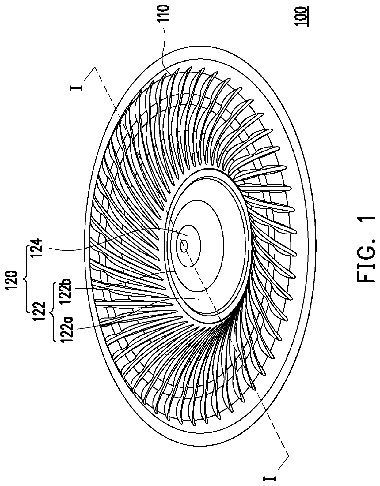
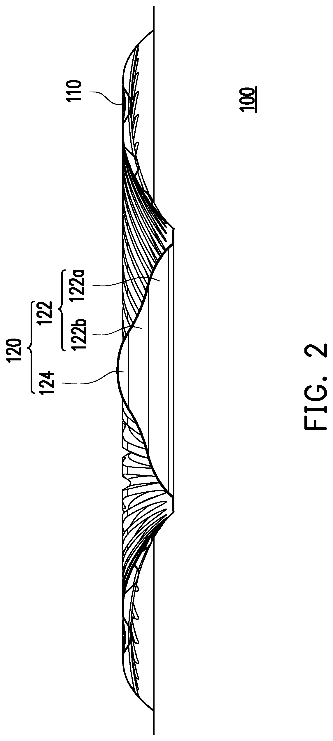
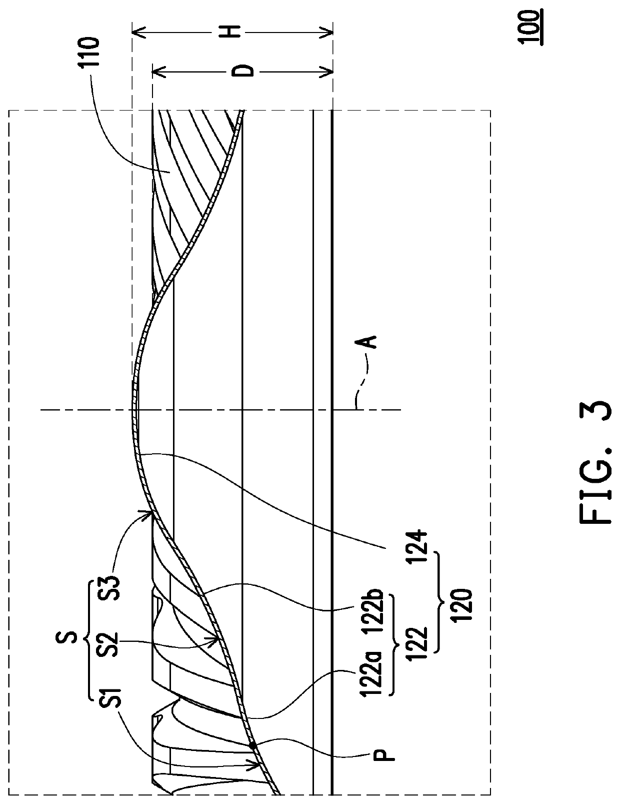
[0018]FIG. 1 is a three-dimensional view of a diaphragm structure according to an embodiment of the disclosure. FIG. 2 is a cross-sectional view of a diaphragm structure of FIG. 1 along line I-I. Referring to FIG. 1 and FIG. 2, a diaphragm structure 100 of the present embodiment includes a suspension side edge 110 and a central part 120. The suspension side edge 110 is connected to a periphery of the central part 120 and surrounds the central part 120. The central part 120 includes a main body part 122 and a structural strengthening part 124. The structural strengthening part 124 is formed at a top end of the main body part 122 so as to increase a structural rigidity of the central part 120. Accordingly, co...


PUM


Abstract

A diaphragm structure including a suspension side edge and a central part is provided. The suspension side edge is connected to a periphery of the central part and surrounds the central part. The central part includes a main body part and a structural strengthening part, and the structural strengthening part is formed at a top end of the main body part.

Description

CROSS-REFERENCE TO RELATED APPLICATION[0001]This application claims the priority benefit of Taiwan application serial no. 110102440, filed on Jan. 22, 2021. The entirety of the above-mentioned patent application is hereby incorporated by reference herein and made a part of this specification.BACKGROUND1. Technical Field[0002]The disclosure relates to a diaphragm structure, and particularly to a diaphragm structure including a suspension side edge and a central part.2. Description of Related Art[0003]Speakers generally include a diaphragm, which is driven by the interaction of the magnetic field generated by the current coil and the magnet, which squeezes the air and converts the mechanical vibration into sound. The material, vibration location and geometric shape of the diaphragm have an effect on the frequency response of the sound in different frequency bands. However, nowadays, most diaphragms are made of a single material, which makes it difficult to meet the different rigidity ...

Claims


Application Information

Patent Timeline
Patent Type & Authority Applications(United States)
IPC IPC(8): G02B5/00
CPCG02B5/005H04R7/127H04R7/14H04R1/38
Inventor LAI, TSAI TI
Owner MERRY ELECTRONICS (SHENZHEN) CO LTD
Why Eureka
Try Eureka