Acoustic wave filter

Pending Publication Date: 2022-07-28
MURATA MFG CO LTD
View PDF0 Cites 0 Cited by
  • Summary
  • Abstract
  • Description
  • Claims
  • Application Information

AI Technical Summary

Benefits of technology

[0008]Each of the acoustic wave filters according to preferred embodiments of the present invention

Problems solved by technology

In the integrated filter disclosed in Japanese Unexamined Patent Application Publication No. 2007-037102, however, the SAW resonator and

Method used


Image

  • Acoustic wave filter
  • Acoustic wave filter
  • Acoustic wave filter

Examples


Example

[0023]Hereinafter, preferred embodiments of the present invention will be described in detail with reference to the drawings. The preferred embodiments described below are comprehensive or specific examples. Specific features including numerical values, shapes, materials, elements, arrangements of the elements, and connection configurations described in the following preferred embodiments are mere examples and are not intended to limit the present invention. Among the elements in the following preferred embodiments, elements not recited in any of the independent claims are described as arbitrary or optional elements. The size or size ratio of the elements illustrated in the drawings is not necessarily presented in an exact manner.

Preferred Embodiment

1. Basic Structure of Acoustic Wave Filter 1

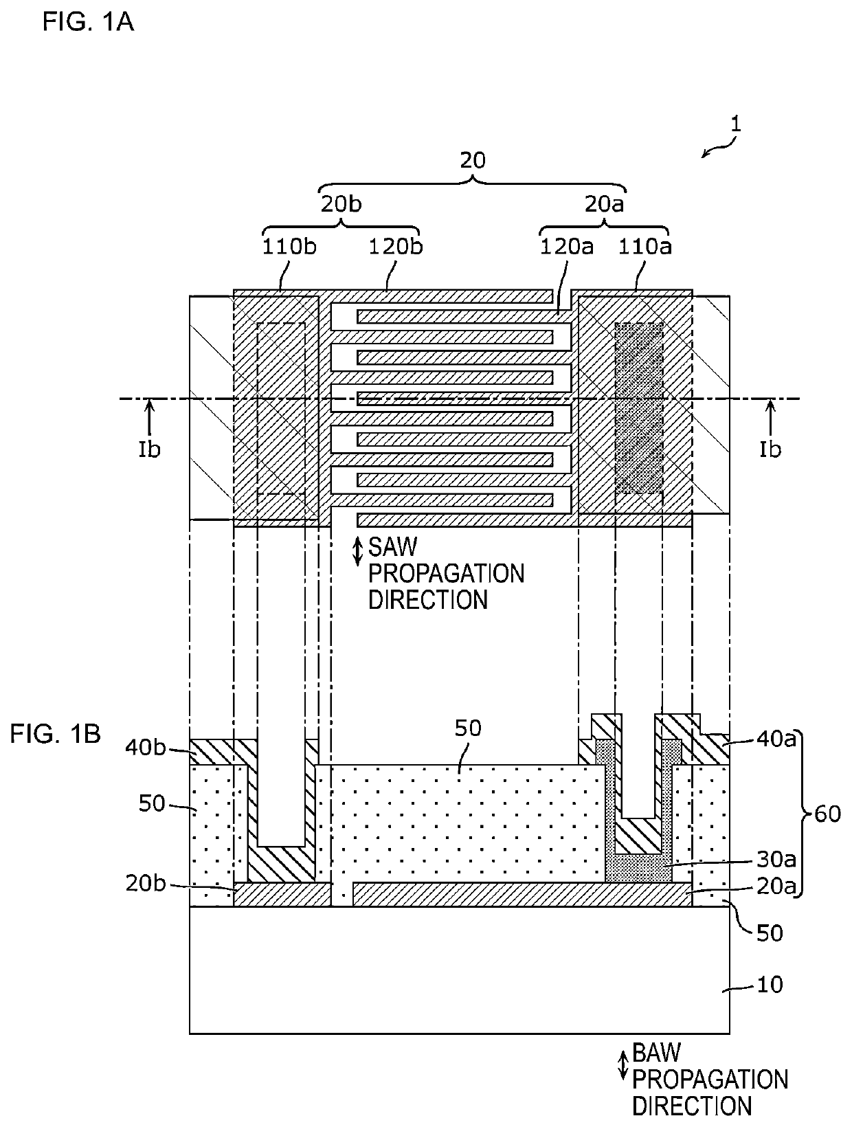
[0024]FIGS. 1A and 1B provide plan views of an electrode and a sectional view of a structure that illustrate a basic structure of an acoustic wave filter 1 according to a first preferred embodi...


PUM


Abstract

An acoustic wave filter includes a surface acoustic wave resonator and a bulk acoustic wave resonator. The SAW resonator includes a piezoelectric substrate and an interdigital transducer electrode on the substrate. The IDT electrode includes a pair of comb-shaped electrodes interdigitated with each other. Each comb-shaped electrode includes electrode fingers extending in parallel or substantially in parallel in a direction crossing the SAW propagation direction and a busbar electrode connecting the electrode fingers to each other at one end of each of the electrode fingers. The BAW resonator includes a lower electrode defined by a portion of a busbar electrode, a piezoelectric film on the busbar electrode, and an upper electrode on the piezoelectric film.

Description

CROSS REFERENCE TO RELATED APPLICATIONS[0001]This application claims the benefit of priority to Japanese Patent Application No. 2019-199253 filed on Oct. 31, 2019 and is a Continuation Application of PCT Application No. PCT / JP2020 / 040849 filed on Oct. 30, 2020. The entire contents of each application are hereby incorporated herein by reference.BACKGROUND OF THE INVENTION1. Field of the Invention[0002]The present invention relates to an acoustic wave filter including a surface acoustic wave resonator and a bulk acoustic wave resonator.2. Description of the Related Art[0003]Low-loss and high-attenuation acoustic wave filters such as longitudinally coupled surface acoustic wave (SAW) filters and SAW ladder filters are used in communication devices, including mobile phones. In recent years, along with the development of multiband operation of communication devices, demand has increased for miniaturized acoustic wave filters usable in various frequency bands.[0004]Japanese Unexamined Pat...

Claims


Application Information

Patent Timeline
IPC IPC(8): H03H9/64H03H9/02H03H9/145H03H9/25
CPCH03H9/6433H03H9/02992H03H9/02559H03H9/25H03H9/145H03H9/6436H03H9/564H03H9/02015H03H9/132
Inventor KAWANO, SHUICHI
Owner MURATA MFG CO LTD
Why Eureka
Try Eureka