
Magnetoelectric surface-acoustic-wave magnetic-field sensor and manufacturing method thereof

A magnetic field sensor and surface acoustic wave technology, which is applied to the size/direction of the magnetic field and the use of electromagnetic devices for magnetic field measurement, etc., can solve the problems of insufficient size, increased charge noise, unstable interface bonding force, etc., and achieves a simple preparation method. , Easy to operate, strong practical effect

Active Publication Date: 2014-12-10
UNIV OF ELECTRONICS SCI & TECH OF CHINA
View PDF7 Cites 32 Cited by
  • Summary
  • Abstract
  • Description
  • Claims
  • Application Information

AI Technical Summary

Problems solved by technology

However, there are still three problems in this type of sensor at present: 1) The composite material with the best performance in the prior art is bonded and formed, and its interfacial bonding force is unstable, and its performance is easily affected by the process and environment. 2) The magnetoelectric effect is related to the volume of the piezoelectric phase, and as the volume of the piezoelectric phase shrinks, the charge noise increases rapidly, so it is difficult to realize the miniaturization of the device; 3) The magnetoelectric coupling coefficient is related to the frequency of the magnetic field , the best magnetoelectric coupling coefficient only exists in a narrow frequency range, it is difficult to detect low frequency AC magnetic field and DC magnetic field with high sensitivity
However, the traditional magnetoacoustic surface wave device directly uses the magnetostrictive effect to change the wavelength λ of the surface acoustic wave. Since λ is limited by the design and microfabrication capability of the interdigital transducer, it cannot be small, and the large magnetostrictive It is also required to apply a large magnetic field, so Δλ / ΔH is not large enough to achieve -7 The magnetic field sensitivity of T, wherein, ΔH is the change of the applied magnetic field H along the direction of the hard axis of the magnetostrictive substrate. Therefore, there is an urgent need for a magnetoelectric acoustic surface wave magnetic field sensor and its preparation method to develop a sensor with high sensitivity and good consistency. Miniaturized magnetoelectroacoustic surface wave magnetic field sensor

Method used


Image

  • Magnetoelectric surface-acoustic-wave magnetic-field sensor and manufacturing method thereof
  • Magnetoelectric surface-acoustic-wave magnetic-field sensor and manufacturing method thereof
  • Magnetoelectric surface-acoustic-wave magnetic-field sensor and manufacturing method thereof

Examples


Embodiment 1

[0043] In this example, the method for preparing a magnetoelectric acoustic surface wave magnetic field sensor comprises the following steps:

[0044] 1) Fe with a thickness of 25 microns 81 Si 13.5 B 3.5 The magnetostrictive amorphous strip of C is used as the magnetostrictive substrate, its thickness is greater than 2 times the wavelength of the surface acoustic wave, the magnetostrictive coefficient is 35ppm, the coercive force along the easy magnetization direction is 80 %; Then use a polishing machine to polish the surface of the magnetostrictive strip, and the polishing solution uses 50nm SiO 2 Suspend the polishing solution, then wash the magnetostrictive strip with absolute ethanol in a high-power ultrasonic machine for 10 minutes, and finally wash it with N 2 Blow dry the magnetostrictive amorphous ribbon.

[0045] 2) in Fe 81 Si 13.5 B 3.5 A 20 nm titanium buffer layer was deposited on C by sputtering.

[0046] 3) A c-axis oriented ZnO piezoelectric thin film...

Embodiment 2

[0050] In this example, the method for preparing a magnetoelectric acoustic surface wave magnetic field sensor comprises the following steps:

[0051] 1) Fe with a thickness of 20 microns 80 Si 9 B 11 The magnetostrictive amorphous strip is used as the magnetostrictive substrate, its thickness is greater than 2 times the wavelength of the surface acoustic wave, the magnetostriction coefficient is 30ppm, the coercive force along the easy magnetization direction is 2Oe, and the remanence ratio is >79.8%; Then use a polishing machine to polish the surface of the magnetostrictive strip, and the polishing solution uses 50nm SiO 2 Suspend the polishing solution, then wash the magnetostrictive strip with absolute ethanol in a high-power ultrasonic machine for 10 minutes, and finally wash it with N 2 Blow dry the magnetostrictive amorphous ribbon.

[0052] 2) in Fe 80 Si 9 B 11 A 20nm titanium buffer layer was sputter deposited on top.

[0053] 3) PZT (Pb 1.1 (Zr 0.58 Ti 0....


PUM

PropertyMeasurementUnit
Thicknessaaaaaaaaaa
Thicknessaaaaaaaaaa
Magnetostriction coefficientaaaaaaaaaa

Abstract

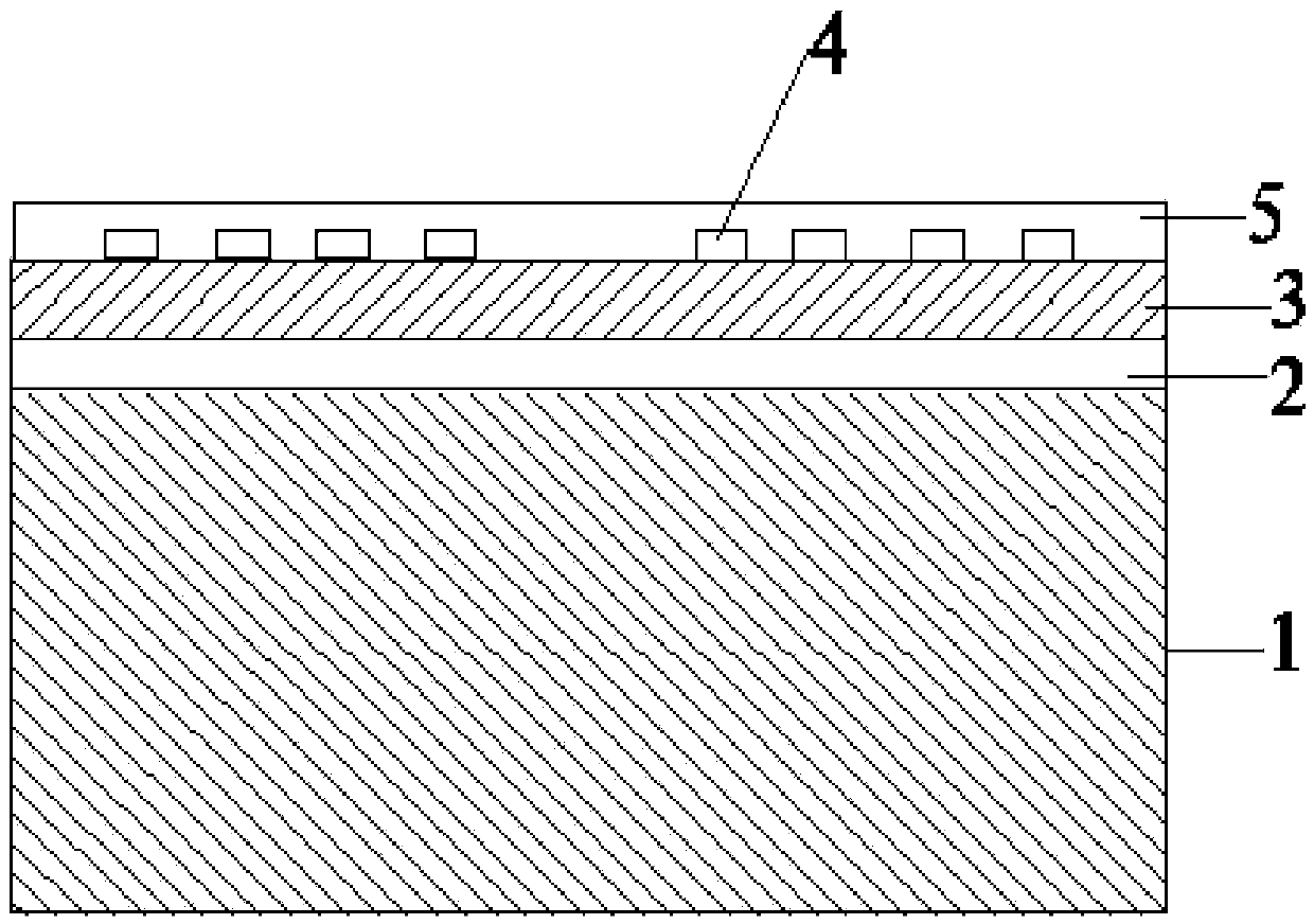
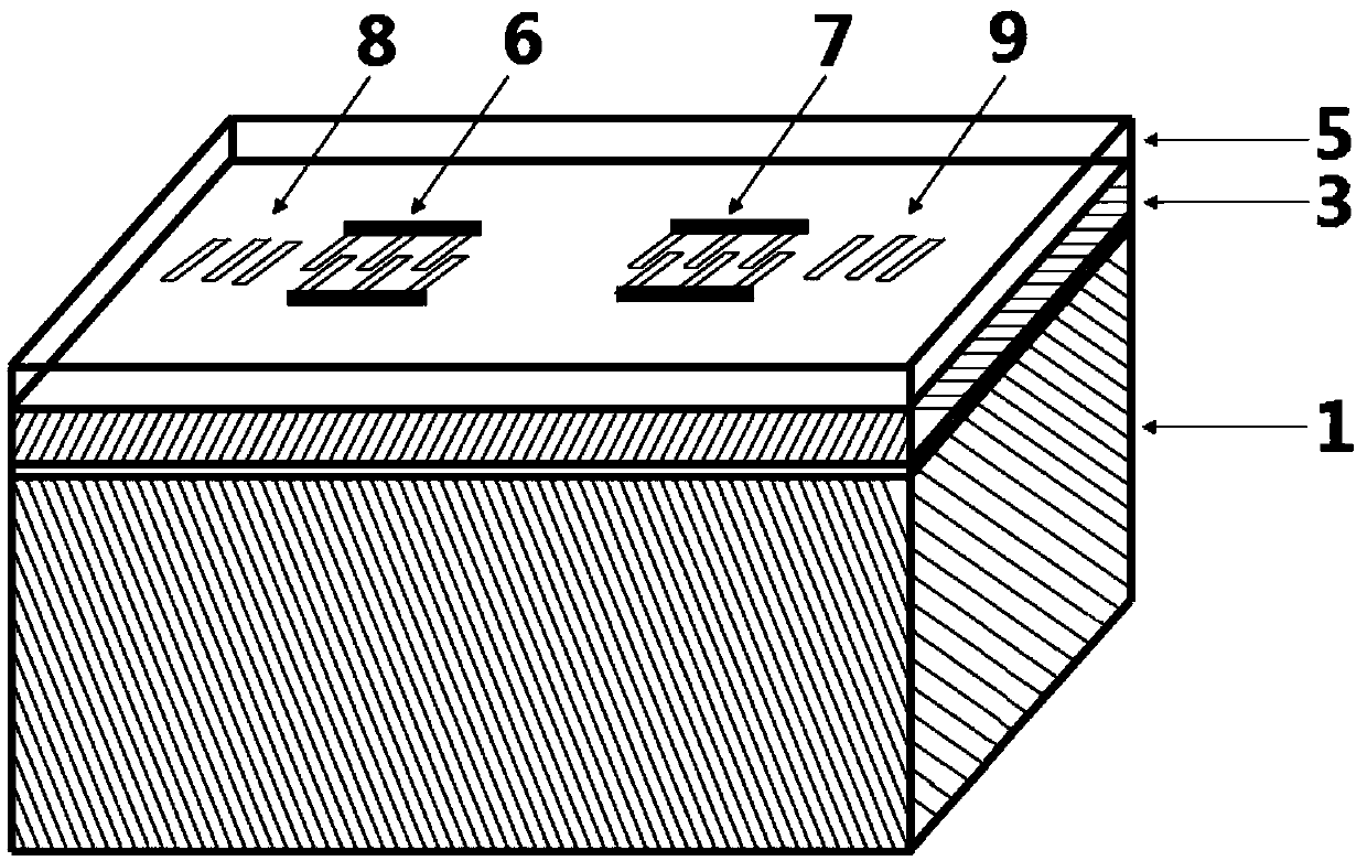
The invention discloses a magnetoelectric surface-acoustic-wave magnetic-field sensor and a manufacturing method thereof and belongs to the technical field of electronic function materials and devices. The magnetoelectric surface-acoustic-wave magnetic-field sensor comprises a magnetostriction substrate, a metal buffer layer and a piezoelectric film, wherein the metal buffer layer is made of metallic titanium or chromium and arranged between the magnetostriction substrate and the piezoelectric film, interdigital transducers with two ports are arranged on the upper surface of the piezoelectric film, and the interdigital transducers and the piezoelectric film constitute a surface-acoustic-wave resonator. Each interdigital transducer comprises an input electrode, an output electrode, an input-end reflecting grating and an output-end reflecting grating, wherein the input-end reflecting grating is arranged on the outer side of the input electrode, and the output-end reflecting grating is arranged on the outer side of the output electrode. The thickness of the piezoelectric film ranges from 0.3-1 micrometer, the thickness of the magnetostriction substrate is larger than two times of wavelength of the surface-acoustic waves. By the aid of the high-orientation piezoelectric film and magnetostriction strips with uniaxial anisotropism and Young's modulus effect, the sensor is miniaturized, high in sensitivity and good in consistency. The manufacturing method is simple and applicable to probing of magnetic fields.

Description

technical field [0001] The invention belongs to the technical field of electronic functional materials and devices, and relates to a magnetoelectric acoustic surface wave magnetic field sensor and a preparation method thereof, in particular to a magnetoelectric sensor with extremely high magnetic field sensitivity based on piezoelectric film and magnetostrictive tape. A surface acoustic wave magnetic field sensor and a preparation method thereof. Background technique [0002] A magnetic field sensor is a device that can convert various magnetic fields and their changes into electrical signal output. Traditional magnetic field sensors include coils, Hall devices, fluxgates, magnetoresistive devices, protons, optical pumps, superconducting quantum interferometers (SQUIDs), etc. The magnetic field sensitivity of the coil, Hall device, and magnetoresistive detector is relatively low; the sensitivity of the fluxgate can reach 10 -10 T, its application range is also relatively w...

Claims


Application Information

Patent Timeline
IPC IPC(8): G01R33/06
Inventor 白飞明黄亮文丹丹钟智勇张怀武
Owner UNIV OF ELECTRONICS SCI & TECH OF CHINA
Learn More