
Frequency divider circuit

a frequency divider and circuit technology, applied in the field of frequency divider circuits, can solve the problems of increasing complexity, increasing the difficulty of clock skew in parallel transmission, and restricting the operation speed of the dff, so as to improve the signal processing speed, facilitate the setup time requirement, and prolong the setup time

Active Publication Date: 2022-07-28
SIGMASTAR TECH LTD
View PDF32 Cites 1 Cited by
  • Summary
  • Abstract
  • Description
  • Claims
  • Application Information

AI Technical Summary

Benefits of technology

The present invention provides a dual-mode frequency divider circuit that has a longer setup time but can achieve a higher signal processing speed as compared to conventional technology. This means that the circuit can easily meet the setup time requirement and process signals quickly.

Problems solved by technology

The processing of multi-phase clocks is also becoming more important and complicated.
In particular, issues such as clock skew in parallel transmission have become increasingly challenging when dealing with Giga-Hertz (GHz)-level high-speed signals.
In general, the operation speed of the DFF is restricted by the setup time.

Method used


Image

  • Frequency divider circuit
  • Frequency divider circuit
  • Frequency divider circuit

Examples


Embodiment Construction

[0022]The following description is written by referring to terms of this technical field. If any term is defined in this specification, such term should be interpreted accordingly. In addition, the connection between objects or events in the below-described embodiments can be direct or indirect provided that these embodiments are practicable under such connection. Said “indirect” means that an intermediate object or a physical space exists between the objects, or an intermediate event or a time interval exists between the events.

[0023]The disclosure herein includes frequency divider circuits. On account of that some or all elements of the frequency divider circuits could be known, the detail of such elements is omitted provided that such detail has little to do with the features of this disclosure, and that this omission nowhere dissatisfies the specification and enablement requirements.

[0024]People having ordinary skill in the art know that the symbol “S” represents the Xth signal ...


PUM


Abstract

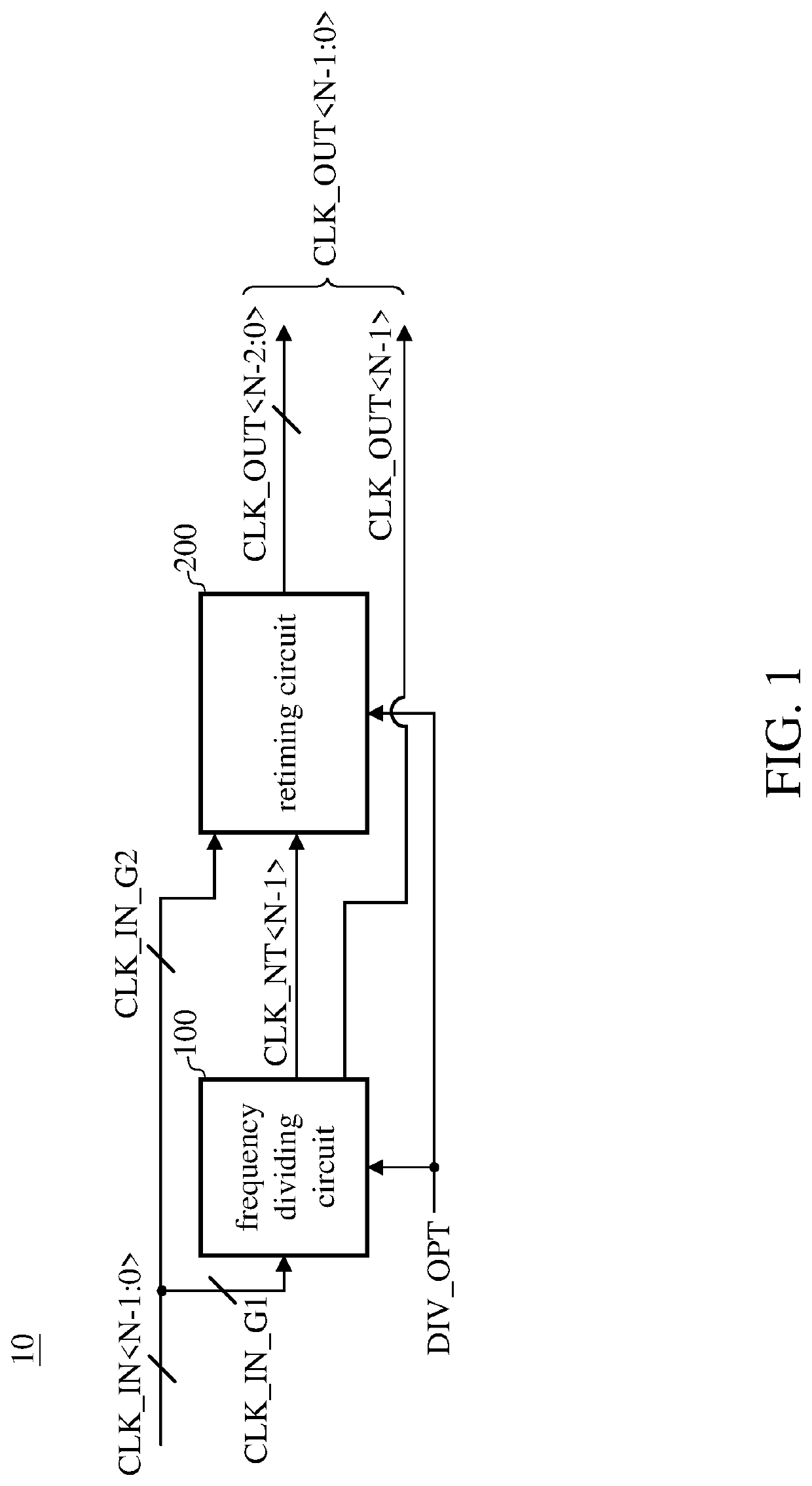
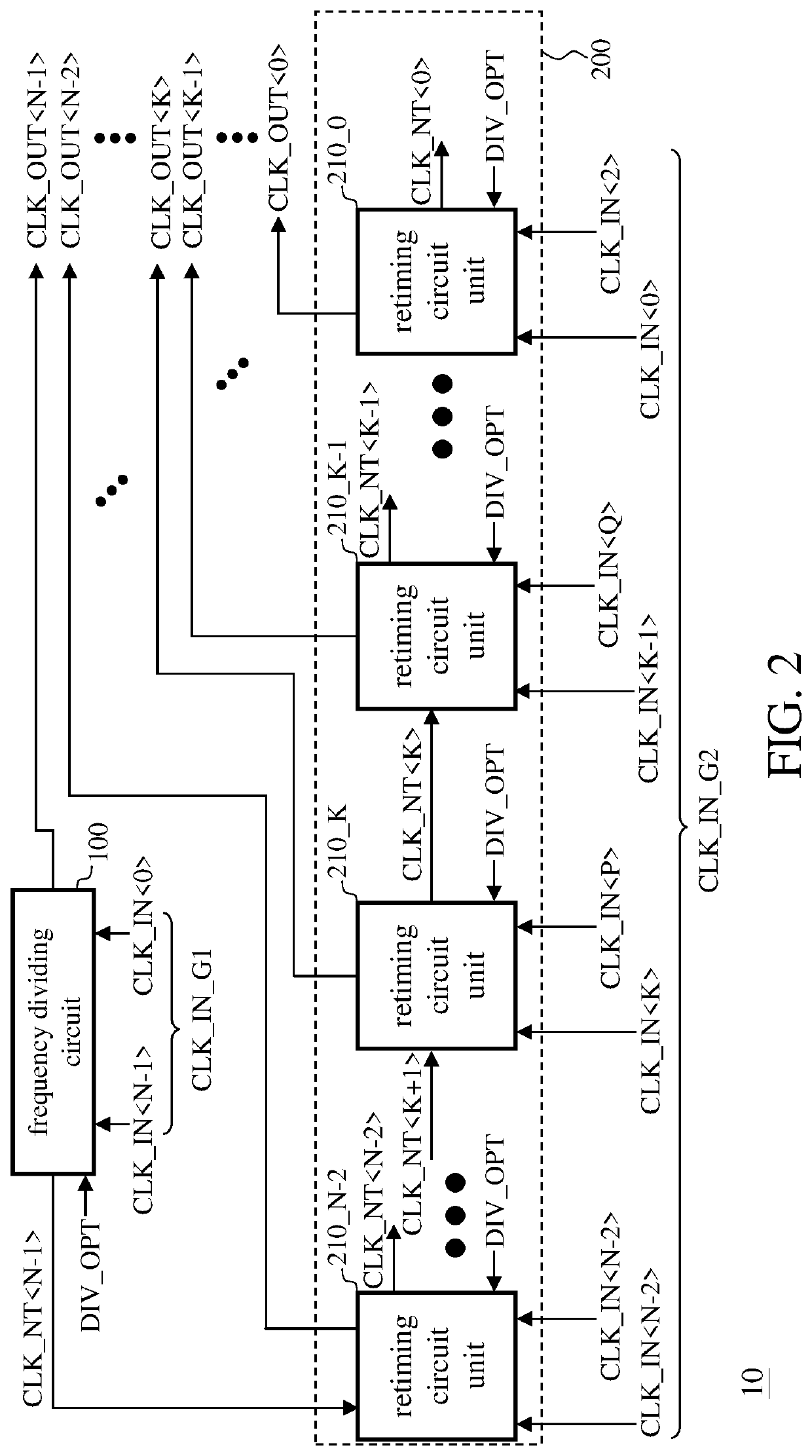
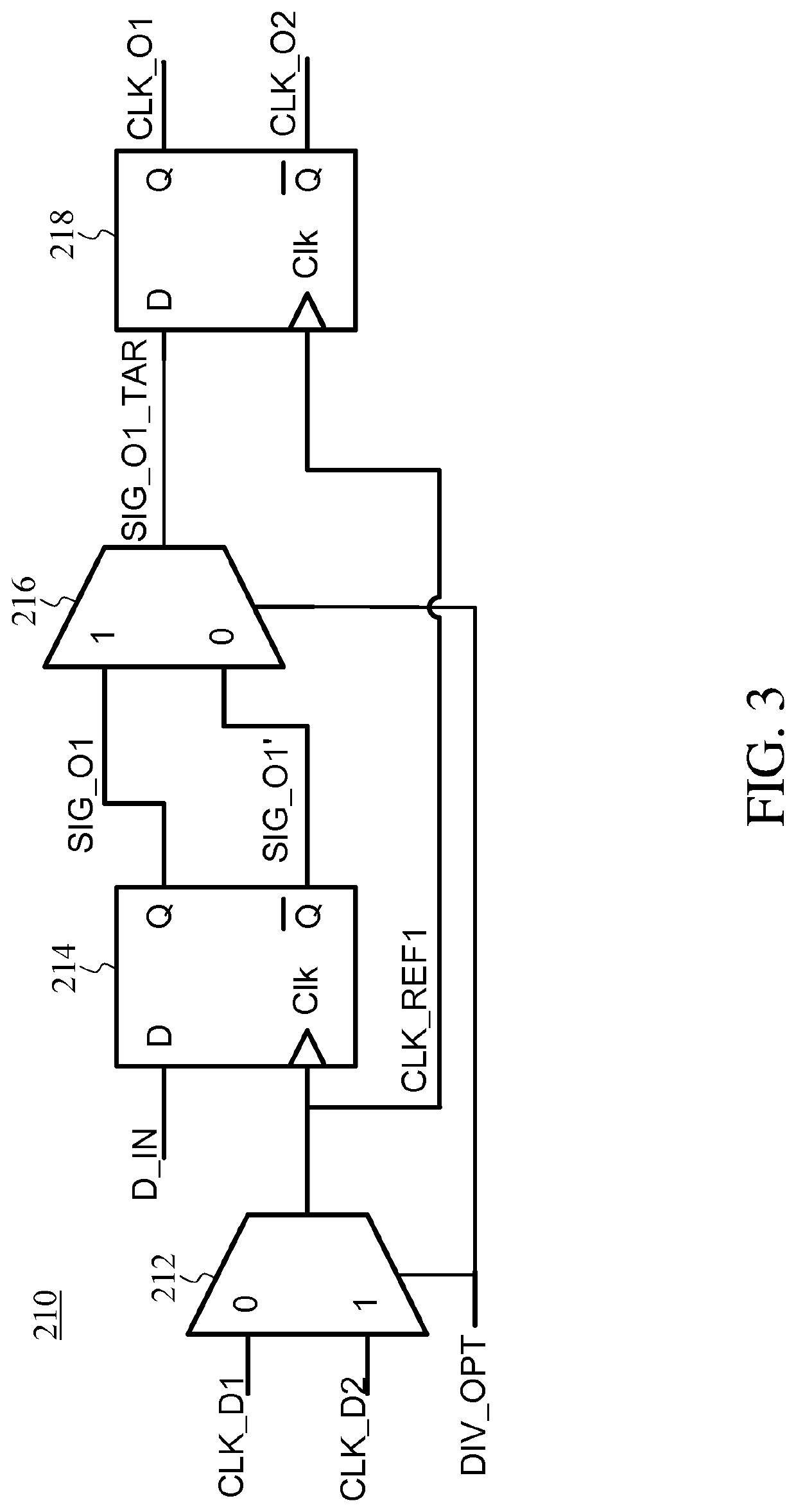
A frequency divider circuit is provided. The frequency divider circuit processes multiple input clocks. The frequency divider circuit includes a frequency dividing circuit and a retiming circuit. The frequency dividing circuit generates an intermediate clock according to a first subgroup of the input clocks. The retiming circuit generates multiple output clocks according to a second subgroup of the input clocks and the intermediate clock. The periods of the input clocks are all a first period, and the periods of the output clocks are all a second period. The first period is smaller than the second period. The frequency dividing circuit and the retiming circuit operate according to a mode control signal which determines a ratio of the first period to the second period.

Description

BACKGROUND OF THE INVENTION1. Field of the Invention[0001]The present invention generally relates to frequency divider circuits, and, more particularly, to multi-phase dual-mode frequency divider circuits.2. Description of Related Art[0002]As the information technology advances, applications such as high-density computing, intensive image processing, and massive data transmission have higher demands on bandwidths for input / output ports. The processing of multi-phase clocks is also becoming more important and complicated. In particular, issues such as clock skew in parallel transmission have become increasingly challenging when dealing with Giga-Hertz (GHz)-level high-speed signals. Thus, an ideal phase relationship should be obtained, which requires the frequency divider circuit to maintain the same input and output time delay when processing multi-path signals of different phases.[0003]Meanwhile, the widely-used frequency divider circuits are usually built with D-Flip Flops (DFFs);...

Claims


Application Information

Patent Timeline
Patent Type & Authority Applications(United States)
IPC IPC(8): H03L7/18
CPCH03L7/18G11C11/4076H03L7/06G11C7/222
Inventor YAO, CHAO-FANSUN, KAI
Owner SIGMASTAR TECH LTD
Learn More