
High-speed signal transmission apparatus

a signal transmission and high-speed technology, applied in the construction details of electrical apparatuses, substation/switching arrangement casings, instruments, etc., can solve the problems of signal transmission loss, inability to perform signal transmission, disabling signal transmission, etc., and achieve the effect of increasing the signal processing speed inside the information processing apparatus

Inactive Publication Date: 2011-06-28
HITACHI METALS LTD
View PDF7 Cites 3 Cited by
  • Summary
  • Abstract
  • Description
  • Claims
  • Application Information

AI Technical Summary

Benefits of technology

The solution enables efficient high-speed signal transmission with reduced loss, broad-band capabilities, and simplified connector management, supporting transmission speeds from 10 to 20 Gbps with low error rates and increased connectivity.

Problems solved by technology

The problem with the method for transmitting a high-speed signal by use of a backboard described in the patent document 1 is that because board wirings are placed between large dielectrics of dielectric loss tangent, which is proper for the formation of a printed circuit board, a transmission loss occurs, disabling the signal transmission.
For example, when a high-speed signal of 10 Gbps is transmitted over the length of 1 m, the amplitude on the receiving side decreases to about 1 / 50, and consequently, it is not possible to perform the signal transmission.
In addition, another problem with the method described in the patent document 1 is that when several hundred signals are transmitted by use of one backboard, the number of wiring lines that can be formed on one layer is exceeded.
The problem with the method for transmitting a high-speed signal between package-mounted housings by use of cables described in the patent document 2 is that cable connectors located at both ends of a cable are not fixed at fixed positions, and therefore, unlike the backboard structure, it is not possible to freely insert and remove the connectors by moving only the daughter board side.
In addition, another problem with the method described in the patent document 2 is that because a motherboard whose impedance matching is difficult to achieve is located between a package connector and a cable connector, a transmission loss occurs when a signal passes through the motherboard, which causes transmission characteristics to be degraded.

Method used


Image

  • High-speed signal transmission apparatus
  • High-speed signal transmission apparatus
  • High-speed signal transmission apparatus

Examples


first embodiment

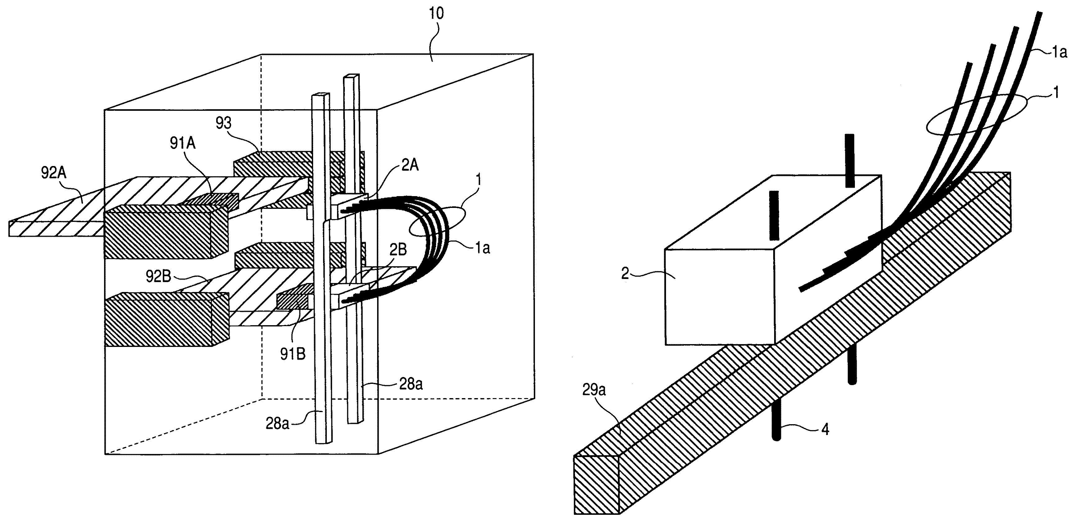
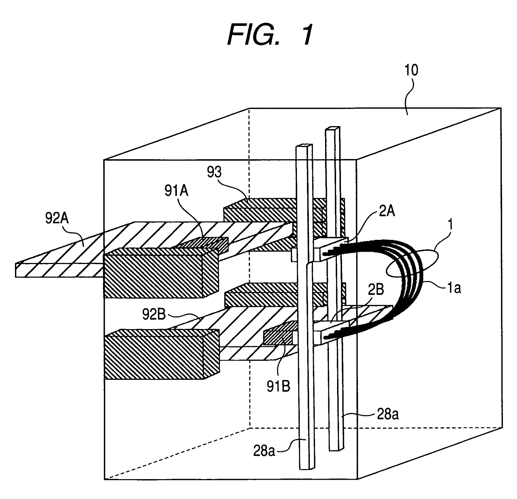
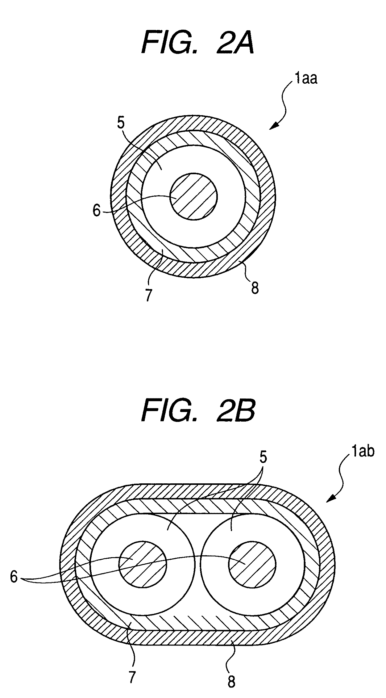
[0029]Elements in a housing, which constitute a high-speed signal transmission apparatus according to a first embodiment of the present invention, will be described with reference to FIGS. 1 through 3. As shown in FIG. 1, a housing 10 accommodates elements constituting a high-speed signal transmission apparatus according to the present invention. A plurality of daughter boards 92A, 92B are formed by printed circuit boards equipped with semiconductor integrated circuits (not illustrated). The daughter boards 92A, 92B which are connected to connectors on the daughter board side (daughter-side connectors) 91A, 91B respectively, are juxtaposed to each other in such a manner that the daughter boards 92A, 92B can be inserted and removed along each daughter rail 93. As a result, a high-speed signal whose transmission speed is about from several Gbps to 20 Gbps is transmitted, through a signal line (not illustrated), from a communication unit (not illustrated) that is formed of, for example...

second embodiment

[0033]Next, elements in a housing, which constitute a high-speed signal transmission apparatus according to a second embodiment of the present invention, will be described with reference to FIGS. 4 through 6. According to the second embodiment of the present invention, as shown in FIG. 4, points of difference between the first and second embodiments are as follows: three or more daughter boards 92A through 92C are juxtaposed to one another in the housing 10; the number of cable bundles (cable groups) 1A, 1B, each of which is used to make a connection between the daughter boards, increases, and accordingly, the number of board-side connectors 91A through 91D and the number of cable-side connectors 2A through 2D also increase; and there is provided a rod-shaped fixing member 29a in the lateral direction that is, for example, a surface direction of the daughter board 92, the rod-shaped fixing member 29a being used to position, for example, the cable-side connectors 2B, 2C, the number o...

third embodiment

[0039]Next, elements in a housing, which constitute a high-speed signal transmission apparatus according to a third embodiment of the present invention, will be described with reference to FIGS. 7 and 8. To be more specific, according to the third embodiment of the present invention, as shown in FIG. 7, points of difference between the second and third embodiments are that instead of the rod-shaped fixing members 28a, 29a, there is provided a stationary plate 28b that is fixed to the housing 10, and that instead of the cable-side connector 2, the cable-side connector block 22a, which is formed by layering wafer-shaped connectors 21a on one another in the lateral direction, is placed into the connector groove 31 formed on the stationary plate 28b. As shown in FIG. 3, each of the wafer-shaped connectors 21a is formed as a connector whose polarity is reverse to that of the board-side connector 91 that is formed by layering wafer-shaped connectors on one another in the lateral direction...


PUM


Abstract

A high-speed signal transmission apparatus comprises: a housing; a plurality of daughter boards juxtaposed to one another in the housing; board-side connectors each provided on corresponding each of the juxtaposed daughter boards; and cable-side connectors fixed in the housing; wherein each of the board-side connectors is insertable / removable into / from corresponding each of the cable-side connectors, and wherein a cable group whose impedance matching can be achieved makes connection between the predetermined cable-side connectors.

Description

BACKGROUND OF THE INVENTION[0001]The present invention relates to high-speed signal transmission apparatus such as a server, a router, a storage unit, or an image processing apparatus, the high-speed signal transmission apparatus being capable of transmitting a high-speed signal inside a housing thereof.[0002]The conventional electronic equipment is known in JP-A-7-221475 (patent document 1). According to the patent document 1, a printed circuit board which is called a daughter board is provided with a CPU and a network port, and a connection between daughter boards is made by another printed circuit board which is called a backboard for information transfer. Thus, the backboard structure has the high maintainability. For example, if electronic equipment fails, it is possible to conveniently replace a daughter board.[0003]In addition, the wiring system which uses a wiring housing is known in JP-A-8-288663 (patent document 2). According to the patent document 2, cables are used to co...

Claims


Application Information

Patent Timeline
Patent Type & Authority Patents(United States)
IPC IPC(8): H02B1/26H05K7/14
CPCH05K7/1458G06F1/185
Inventor YAMAMOTO, KEIICHICHUJO, NORIOKUMAKURA, TAKASHIISHIMATSU, YOSUKE
Owner HITACHI METALS LTD
Learn More