Method for generating control signals for an image capture device

a control signal and image capture technology, applied in the field of image capture device control signal generation, can solve the problems of not necessarily intended embodiments, inability to connect all image capture apparatuses to a central image processing device, and harsh stadium environmen

Pending Publication Date: 2022-07-28
CANON KK
View PDF2 Cites 0 Cited by
  • Summary
  • Abstract
  • Description
  • Claims
  • Application Information

AI Technical Summary

Benefits of technology

[0018]When a failure occurs, i.e., a loss of synchronization is detected, the reference clock used for generating the control signals is changed to advantageously ensure a continuity in the generation of control signals. Such method enables the generation of control signals resilient to failures, in particular to successive failures, without having to duplicate all hardware. The change of reference clock for generating the control signals takes place transparently and almost instantaneously, which minimizes—or even eliminates—frame losses. Therefore, the above method is fast, robust to failures, and relatively inexpensive.

Problems solved by technology

Furthermore, all embodiments are not necessarily intended to solve all or even any of the problems brought forward in this section.
Because of that, it is not possible to connect all the image capturing apparatuses to a central image processing device by a conventional image capture interconnect technology, such as Serial Digital Interface (SDI).
However, stadium environment may be harsh and network cables may suffer temporary or permanent damages, while the coverage of the sporting event must continue without interruption.
According to this mechanism, when a network and / or time server failure occurs, the protocol stack times out because the time server is not reachable.
However, these solutions have drawbacks.
On the one hand, duplicating the hardware may be very costly (e.g., when the whole synchronization device is duplicated).
On the other hand, switching from one equipment to a backup equipment can be very long compared to the targeted applications.

Method used


Image

  • Method for generating control signals for an image capture device
  • Method for generating control signals for an image capture device
  • Method for generating control signals for an image capture device

Examples


Embodiment Construction

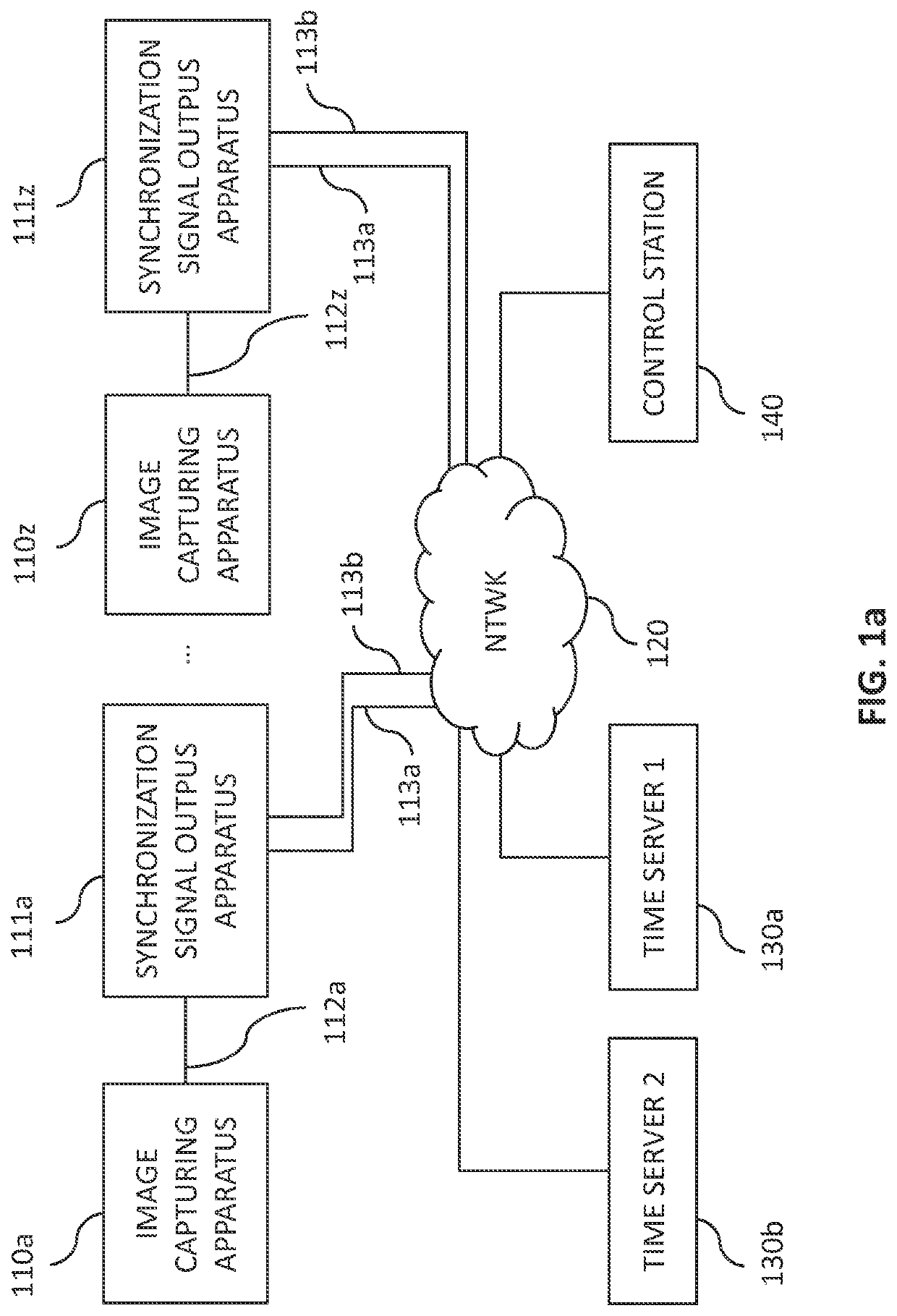
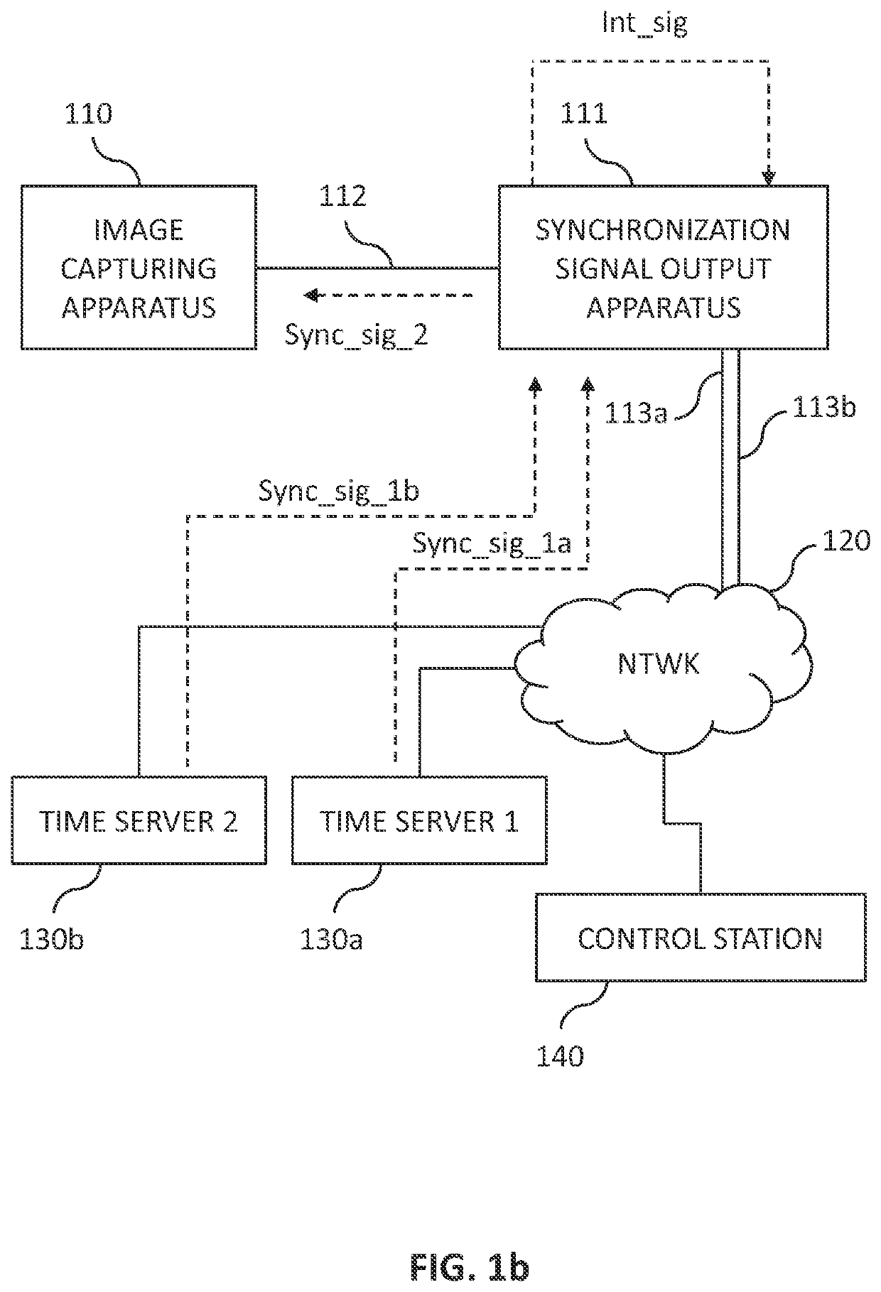
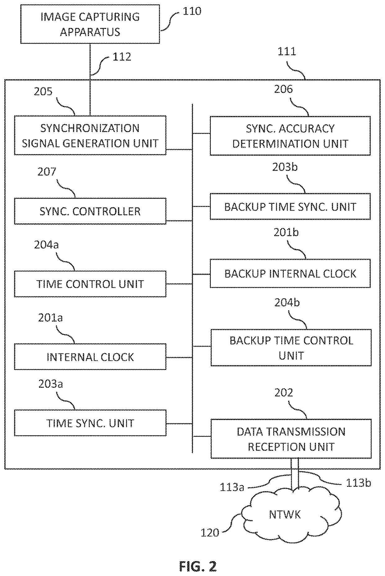
[0049]According to embodiments, the invention proposes to duplicate only certain elements of an image capture system to maintain reliably image capture in the event of failures. More specifically, the system may use two time servers for providing a time reference so that all capture devices are synchronized with each other. Also, the communication devices, which control the capture times of the image capture devices, each has two slave time generators that can be used for generating control signals for the image capture devices. Schematically, a slave time generator is an entity associated with a clock, capable of generating clock signals from which control signals may be generated for image capture devices. In the example of FIG. 2, a slave time generator may comprise a time synchronization unit 203a (resp. 203b) and an internal clock 201a (resp. 201b). The slave time generator may also comprise a time control unit 204a (resp. 204b). When possible, the two slave time generators are...


PUM


Abstract

The present invention relates to a method for generating control signals for an image capture device, the method being performed in a communication device comprising a first slave time generator and a second slave time generator, the communication device being connected to a first remote time server and a second remote time server, the method comprising:synchronizing the first slave time generator with the first remote time server;synchronizing the second slave time generator with the second remote time server;generating a first control signal based on the first clock, and sending the first control signal to the image capture device; andupon detecting a loss of synchronization between the first slave time generator and the first remote time server, generating a second control signal based on the second clock, and sending the second control signal to the image capture device.

Description

CROSS REFERENCE TO RELATED APPLICATION[0001]This application claims the benefit under 35 U.S.C. § 119(a)-(d) of United Kingdom Patent Application No. 2100900.6, filed on Jan. 22, 2021 and entitled “Method for generating control signals for an image capture device”. The above cited patent application is incorporated herein by reference in its entirety.FIELD OF THE INVENTION[0002]The present invention relates to a method, a device, and a computer program for maintaining the generation of control signals by a communication device when a network failure occurs, thereby reducing the number of images not captured by an image capture device connected to this communication device.BACKGROUND OF THE INVENTION[0003]The approaches described in this section could be pursued, but are not necessarily approaches that have been previously conceived or pursued. Therefore, unless otherwise indicated herein, the approaches described in this section are not prior art to the claims in this application an...

Claims


Application Information

Patent Timeline
Patent Type & Authority Applications(United States)
IPC IPC(8): H04N13/296H04J3/06
CPCH04N13/296H04J3/0641H04N21/21805H04N5/0733H04N21/2187H04N21/4305H04N21/816H04N21/4223H04N23/90H04J3/0688G06F11/1604H04N5/06G06F11/1679H04N23/661G06F1/12H04N23/662
Inventor EL KOLLI, YACINEGUIGNARD, ROMAINHALNA DU FRETAY, TRISTANTOCZE, LIONEL
Owner CANON KK
Why Eureka
Try Eureka