
Mobile foundation for tower cranes and fast-erecting cranes

a technology for mobile foundations and cranes, which is applied in the direction of propulsion parts, transportation and packaging, and electric propulsion mounting, etc. it can solve the problems of uneconomic, uneconomic erecting crane foundations, and uneconomic concrete foundations, etc., and achieves low weight, and high strength and rigidity.

Pending Publication Date: 2022-08-04
KAINZMAYER THOMAS
View PDF0 Cites 0 Cited by
  • Summary
  • Abstract
  • Description
  • Claims
  • Application Information

AI Technical Summary

Benefits of technology

The invention provides a mobile foundation for tower cranes and fast-erecting cranes that is stable against wind loads and net crane loads, while still being lightweight. The floor elements of the foundation are connected to each other by beams, which can be welded to one another, or configured as H-beams or T-beams. The floor elements can also have cover plates and base plates that are connected to the beams for increased strength and rigidity. The mobile foundation has transportable ballast weights and a support surface for the weights, which can be easily assembled and disassembled. The invention also provides a passage element with uprights and / or side walls that can be releasably connected to the floor elements, and is strong and rigid enough to support the weights. The passage element can also have a cover plate at the upper end to protect pedestrians.

Problems solved by technology

These concrete foundations, however, have to be destroyed, loaded, transported off and disposed of upon completion of the construction site and disassembly of the crane.
This sort of erecting crane foundations is uneconomic as well as ecologically questionable when taking into account that the production of 1 m3 concrete is associated with about 1,000 kg CO2 load for the environment and that the foundation plate of a medium-sized crane is typically composed of 20-40 m3 reinforced concrete and may only be used once.
Furthermore, the foundation plate and the foundation anchors damage pavements and parts of the road, which will have to be repaired following the destructive removal of the concrete foundation.
Another disadvantage of conventional crane foundations made from concrete is that the concrete foundations require heights of 75-150 cm in order to ensure the necessary strength and distribution of the crane loads.
Such high concrete foundations, however, block the pavements, i.e. pedestrian traffic will have to move onto the street or to the opposite street side.
Also vehicle traffic is impaired by necessary constriction or closure of road lanes.

Method used


Image

  • Mobile foundation for tower cranes and fast-erecting cranes
  • Mobile foundation for tower cranes and fast-erecting cranes
  • Mobile foundation for tower cranes and fast-erecting cranes

Examples


Embodiment Construction

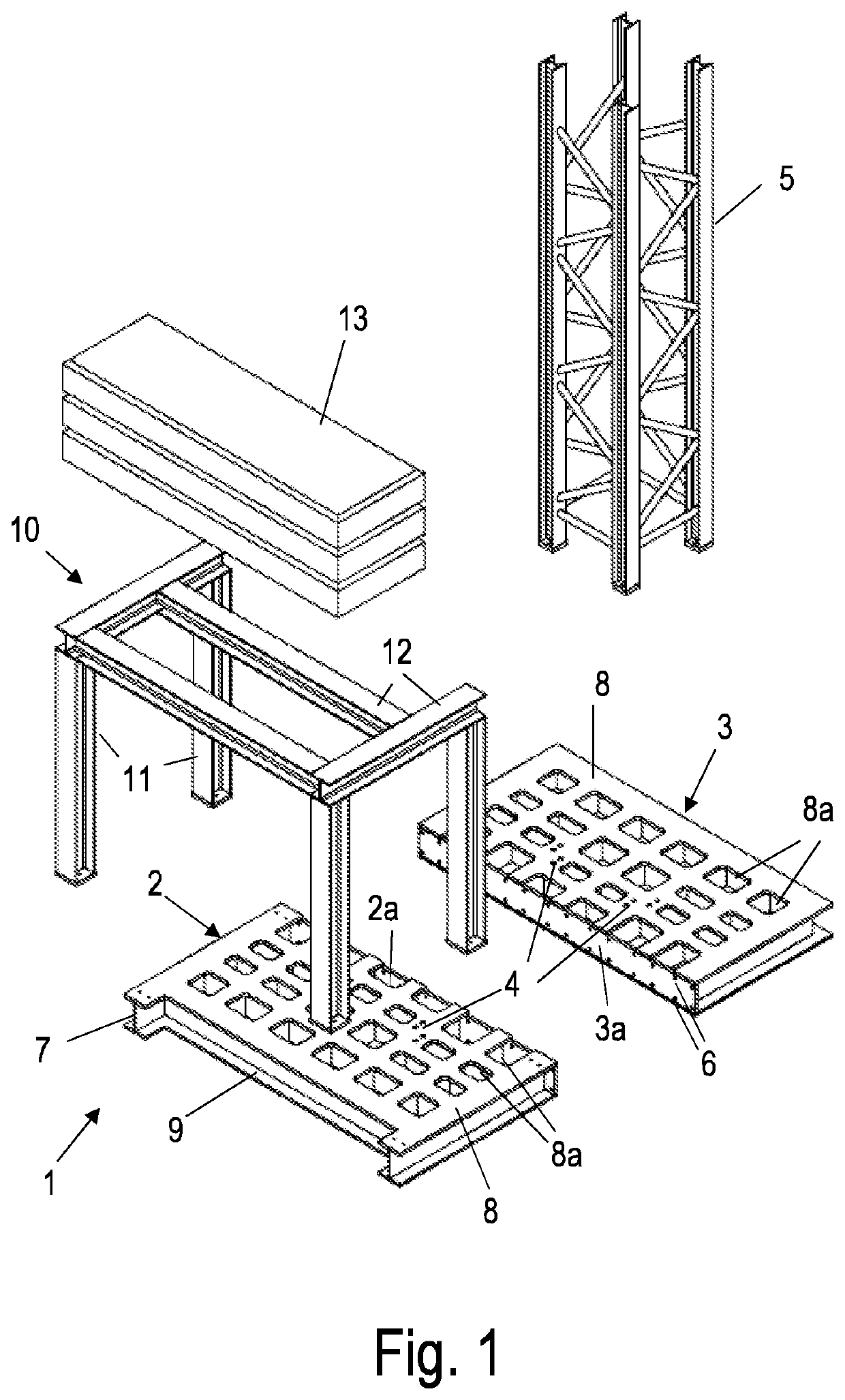
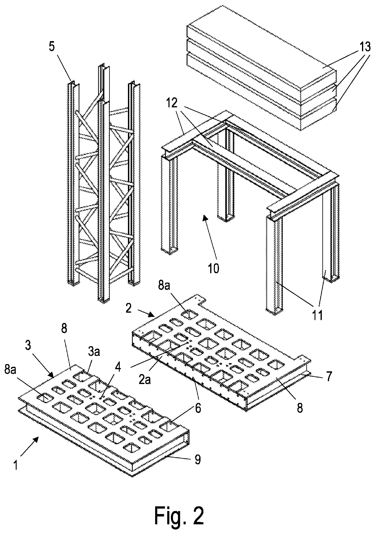
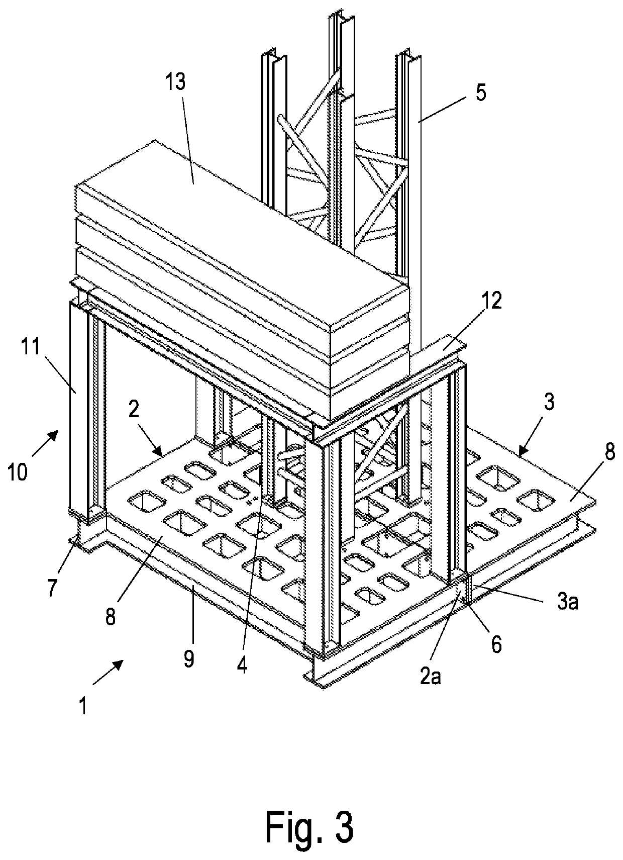
[0020]The exemplary embodiment depicted in the FIGS. 1 to 4 of the inventive mobile foundation for tower cranes and fast-erecting cranes comprises two floor elements 2, 3 made from metal, which may be releasably connected to one another, in particular screwed to one another. The floor elements have anchoring devices 4 for a crane tower 5. The anchoring devices 4 for the crane tower 5 are configured as through-holes, optionally having protection elements against unscrewing of nuts, they may, however, alternatively also comprise holding elements, in particular clamps, attached to the floor elements 2, 3. The crane tower is not an integral part of the present invention but rather a part of a tower crane or fast-erecting crane, for which the foundation 1 forms a temporary foundation.

[0021]The floor elements 2, 3 have side walls 2a, 3a, at which they may be connected to one another. For this purpose, there are provided in the side walls 2a, 3a through-holes 6, wherein the positions of th...


PUM


Abstract

The mobile foundation for tower cranes and fast-erecting cranes comprises at least two floor elements made from metal, which may be releasably connected to one another, in particular screwed to one another, wherein the floor elements have anchoring devices for a crane tower. Transportable, reusable ballast weights may be supported on at least one support surface of the foundation. There is provided a passage element having uprights and / or side walls, wherein the uprights or side walls, respectively, have a height of at least 2.1 m, preferably of at least 2.3 m, wherein the passage element may be releasably connected to the floor elements, in particular screwed thereto.

Description

BACKGROUND OF THE INVENTION[0001]The invention relates to a mobile foundation for tower cranes and fast-erecting cranes. Currently, there have to be cast concrete foundations for the temporary erection of tower cranes and fast-erecting cranes in order to distribute the forces of the crane uniformly via foundation anchors or foundation crosses, respectively, onto the ground. These concrete foundations, however, have to be destroyed, loaded, transported off and disposed of upon completion of the construction site and disassembly of the crane.[0002]This sort of erecting crane foundations is uneconomic as well as ecologically questionable when taking into account that the production of 1 m3 concrete is associated with about 1,000 kg CO2 load for the environment and that the foundation plate of a medium-sized crane is typically composed of 20-40 m3 reinforced concrete and may only be used once. Furthermore, the foundation plate and the foundation anchors damage pavements and parts of the...

Claims


Application Information

Patent Timeline
Patent Type & Authority Applications(United States)
IPC IPC(8): E02D27/44E04F15/06
CPCE02D27/44E04F15/06B66C23/62E02D27/42B60K2015/03315B60K2015/03309B60K15/03B60K15/063B60K2015/0638B60K15/067B60K15/07B60K15/073B60Y2200/148B60Y2200/14B60K1/00
Inventor KAINZMAYER, THOMAS
Owner KAINZMAYER THOMAS
Learn More