Lens mounting apparatus and projector

Pending Publication Date: 2022-08-04
PANASONIC INTELLECTUAL PROPERTY MANAGEMENT CO LTD
View PDF0 Cites 0 Cited by
  • Summary
  • Abstract
  • Description
  • Claims
  • Application Information

AI Technical Summary

Benefits of technology

The present invention is a lens mounting apparatus that aims to reduce the size of the socket, prevent contact failure of the socket, improve the mounting of the lens, and make the operation simpler for users. Additionally, the invention includes a projector that utilizes this lens mounting apparatus. The apparatus includes a first elastic member that pushes the socket towards the center, increasing the effective stroke of the socket contact and reducing contact failure rates. The lens is inserted without coming into contact with the socket, preventing deformation of the socket contact. The lens does not need to be rotated after insertion, improving mounting operability, especially for lenses with heavy weight. Finally, the socket is movable radially, making it small in size and cost-effective.

Problems solved by technology

However, Unexamined Japanese Patent Publication No. 2012-155290 has the following technical problems.
After the lens is inserted, the lens cannot be fixed to the camera without rotating the lens.
Thus, mounting operation of the lens is inconvenient.
In particular, with a lens having a large weight, elasticity of an elastic piece of a lens mount increases, a large force is required to rotate the lens, and the lens cannot be fixed firmly.
An effective stroke of an elastic contact of the socket is small, and the elastic contact of the socket is easily deformed and lost when the lens is rotated, and thus a contact failure easily occurs.
After the lens is inserted, a contact failure rate at the contact decreases.
However, the known art described above has the following technical problems.
The socket needs to freely move in a narrow space such that a position of the socket does not affect positioning of the lens, and thus the socket costs high.
Thus, an effective stroke of the socket contact as the connection part of the socket increases, and a contact failure rate at the contact decreases.

Method used


Image

  • Lens mounting apparatus and projector
  • Lens mounting apparatus and projector
  • Lens mounting apparatus and projector

Examples


Embodiment Construction

[0036]Hereinafter, a structure and a function of each component of the present disclosure will be described in detail with reference to the drawings. In the following description, the same or corresponding members and structures are designated by the same reference numerals, and duplicated description will be omitted.

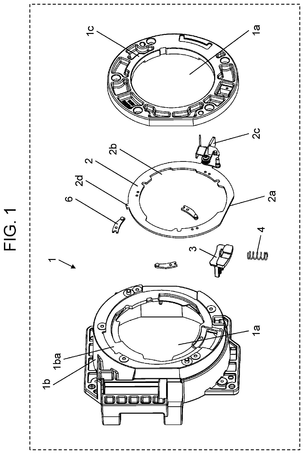
[0037]As illustrated in FIG. 1, a lens mounting apparatus of the present disclosure includes base 1 having opening 1a into which lens 5 (see FIG. 6A described later) is inserted and attached, annular frame 2 provided with notch 2a formed by notching a part of an outer periphery, socket 3 electrically connected to lens contact 5a as a connection part of lens 5, and first elastic member (for example, spring) 4 provided to urge socket 3 from an outer periphery toward a center, that is, a radial center of annular frame 2. Here, lens 5 is a projection lens used in a projector described later. Note that illustration of the lens is omitted in FIG. 1.

[0038]Specifically, as illu...


PUM


Abstract

A lens mounting apparatus includes a base including an opening, wherein a lens including a connection part is inserted and attached, an annular frame including a notch provided on a part of an outer periphery, a socket electrically connected to the connection part of the lens, and a first elastic member provided to urge the socket from the outer periphery toward a center of the annular frame. The annular frame is configured to fix the lens inserted and attached into the base by rotating the annular frame in one direction by a predetermined angle. When the annular frame does not fix the lens, the notch does not face the socket. When the annular frame fixes the lens, the notch faces the socket, and the socket is electrically connected to the connection part of the lens by an urging force of the first elastic member.

Description

BACKGROUND1. Technical Field[0001]The present disclosure relates to a lens mounting apparatus and a projector including the lens mounting apparatus.2. Description of the Related Art[0002]When a lens is mounted on a camera, a projector, or the like, it is necessary to electrically connect a lens contact of the lens and a socket contact of a socket mounted on the camera, the projector, or the like, and to fix the lens to the camera, the projector, or the like.[0003]As a lens mounting apparatus as described above, Unexamined Japanese Patent Publication No. 2012-155290 discloses the following configuration.[0004]In Unexamined Japanese Patent Publication No. 2012-155290, the lens contact and the socket contact are electrically connected to each other by rotating the lens after the lens is inserted into the camera in order to electrically connect the lens contact and the socket contact favorably and prevent the lens from being erroneously mounted on the camera.[0005]Thus, the camera in Un...

Claims


Application Information

Patent Timeline
IPC IPC(8): G02B7/02H01R13/627
CPCG02B7/02H01R13/6272H01R9/18H01R4/4863H01R4/42G03B21/14H01R13/2442H01R9/24G02B7/08G02B7/026G03B21/142G03B21/145
Inventor CHEN, YACHEN, CHEN
Owner PANASONIC INTELLECTUAL PROPERTY MANAGEMENT CO LTD
Why Eureka
Try Eureka