Cooling device and structure

a cooling device and cooling medium technology, applied in the direction of battery/fuel cell control arrangement, lighting and heating apparatus, battery, etc., can solve problems such as deterioration of batteries, and achieve the effect of reducing the risk of leakage of cooling medium and excellent lightweight properties

Pending Publication Date: 2022-08-04
MITSUI CHEM INC
View PDF0 Cites 0 Cited by
  • Summary
  • Abstract
  • Description
  • Claims
  • Application Information

AI Technical Summary

Benefits of technology

[0047]According to the present invention, it is possible to provide a cooling device capable of reducing the risk of leakage of a cooling medium and having an excellent lightweight property, and a structure.

Problems solved by technology

It has been known that high-output and high-capacity batteries generate a large quantity of heat during the course of charging or discharging, and the heat causes deterioration of the battery.

Method used


Image

  • Cooling device and structure
  • Cooling device and structure
  • Cooling device and structure

Examples


Embodiment Construction

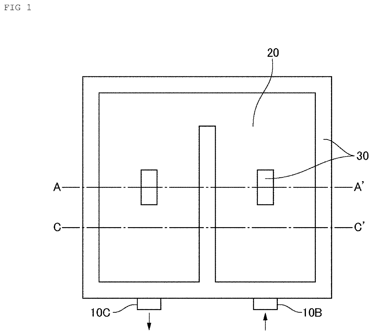
[0053]Hereinafter, embodiments of the present invention will be described using the drawings. In all the drawings, the same constituent elements are denoted by the same reference signs, and description thereof will not be repeated. In addition, the drawings are schematic drawings, and dimension ratios in the drawings are different from the actual dimension ratios. Unless otherwise specified, the symbol “-” between numbers in the sentence represents equal to or more than the number and equal to or less than the other number.

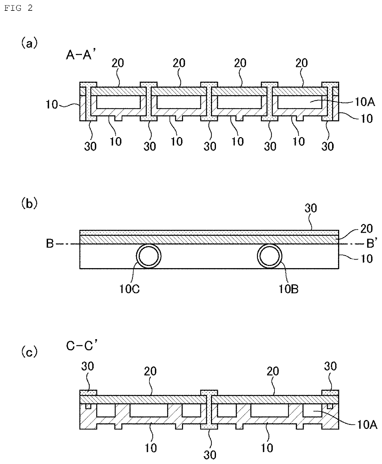
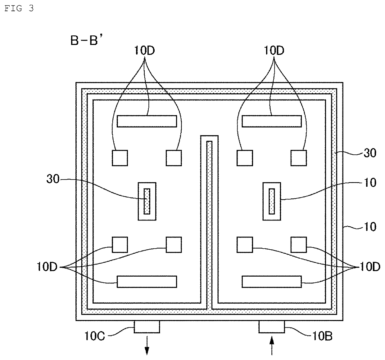
[0054]FIG. 1 is a plan view schematically showing an example of a structure of a cooling device according to this embodiment. FIG. 2 shows (a) a cross-sectional view taken along the line A-A′ of the cooling device shown in FIG. 1, (b) a side view of the cooling device, and (c) a cross-sectional view taken along the line C-C′ of the cooling device. FIG. 3 is a horizontal sectional view taken along the line B-B′ of the cooling device shown in FIG. 2(b).

[0055]The coo...


PUM

PropertyMeasurementUnit
thicknessaaaaaaaaaa
thicknessaaaaaaaaaa
thicknessaaaaaaaaaa

Abstract

A cooling device including: a resin flow path which is provided with a space portion serving as a flow path in at least one surface; a metal cooling panel for cooling a heating element, which covers the space portion and of which at least a part is in contact with the resin flow path; and a resin bonding member for bonding the resin flow path and the metal cooling panel, in which the metal cooling panel has a fine uneven structure at least on a surface of a bonding portion with the resin bonding member, and the metal cooling panel and the resin bonding member are bonded by allowing a part of the resin bonding member to enter into the fine uneven structure.

Description

TECHNICAL FIELD[0001]The present invention relates to a cooling device and a structure.BACKGROUND ART[0002]In recent years, batteries have been attracting attention as a power source for electric vehicles and the like. It has been known that high-output and high-capacity batteries generate a large quantity of heat during the course of charging or discharging, and the heat causes deterioration of the battery. Therefore, the batteries require a cooling system.[0003]In addition, a countermeasure against heat has been thought to be important for electronic components mounted with a semiconductor element, which is a heat generating element. In particular, the power consumption per electronic component has remarkably increased due to the recent tendency toward the miniaturization and high-density packaging of electronic components, or the speeding up of microprocessors, and an efficient cooling system is important.[0004]In recent years, liquid-cooling type cooling devices have been employ...

Claims


Application Information

Patent Timeline
Patent Type & Authority Applications(United States)
IPC IPC(8): H01M10/613H01M10/6554H01M10/6568
CPCH01M10/613B60L58/26H01M10/6568H01M10/6554H01M10/625H01M10/6556F28F21/065F28F21/081H01M2220/20
Inventor KIMURA, KAZUKITOMINAGA, TAKAHIROKURIYAGAWA, MIZUETORII, TOMOKINOMOTO, KYOHEI
Owner MITSUI CHEM INC
Why Eureka
Try Eureka