Cartridge flow rate adjusting assembly with compensating chamber and hydraulic valve comprising the cartridge flow rate adjusting assembly

a flow rate adjusting and cartridge technology, which is applied in the direction of fluid pressure control, pressure relieving devices on sealing faces, instruments, etc., can solve the problems of high hydraulic pressure acting on the closing shutter, consuming more power, and having a size proportional to the high involved for

Pending Publication Date: 2022-08-11
GIACOMINI
View PDF16 Cites 0 Cited by
  • Summary
  • Abstract
  • Description
  • Claims
  • Application Information

AI Technical Summary

Benefits of technology

[0010]An object of the present invention consists of overcoming and obviating, at least partially, the drawbacks and operative limits of the above discussed prior art. Specifically, an object of the present invention consists of providing a cart...

Problems solved by technology

A serious drawback of the valves of the known type is the presence of high hydraulic pressures acting on the closing shutte...

Method used


Image

  • Cartridge flow rate adjusting assembly with compensating chamber and hydraulic valve comprising the cartridge flow rate adjusting assembly
  • Cartridge flow rate adjusting assembly with compensating chamber and hydraulic valve comprising the cartridge flow rate adjusting assembly
  • Cartridge flow rate adjusting assembly with compensating chamber and hydraulic valve comprising the cartridge flow rate adjusting assembly

Examples


Embodiment Construction

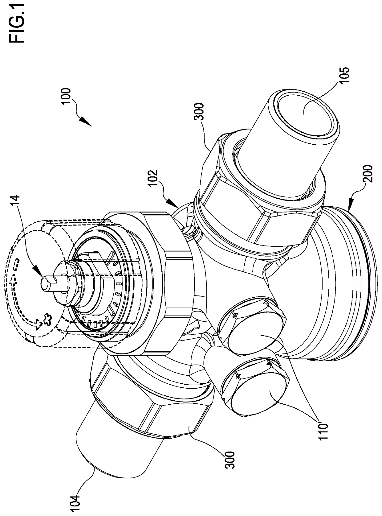
[0025]Referring particularly to the attached figures (particularly to FIGS. 1, 2, 4, 6, 7 and 9), a preferred embodiment of a hydraulic valve 100 of the PICV type (Pressure Independent Control Valve) according to the present invention is shown.

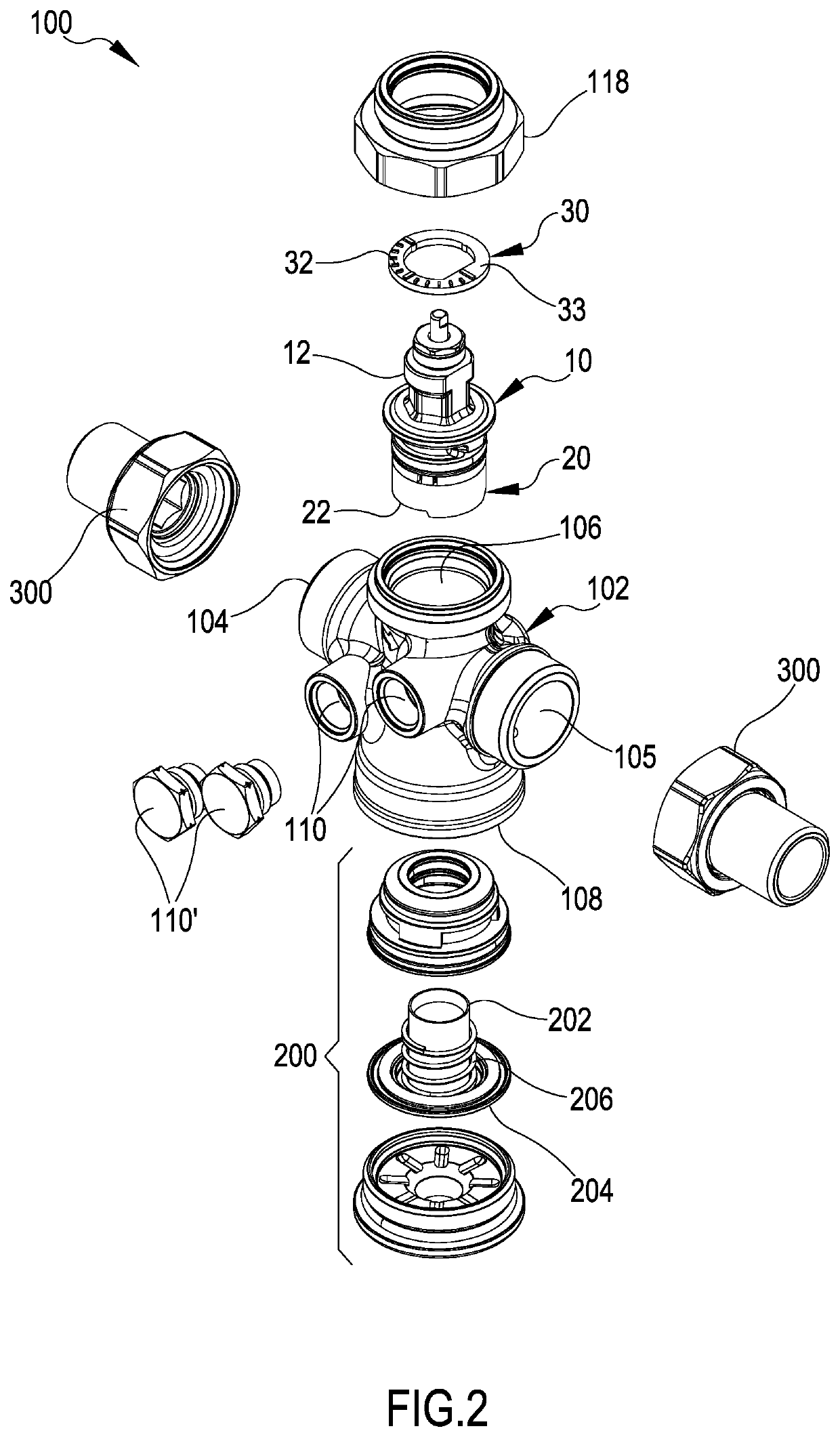
[0026]The valve 100 comprises a valve body 102 having an inlet opening 104, and outlet opening 105 and a handling opening 106. An opening 108, made in the valve body 102 of a valve, particularly of the PICV type, houses a dynamic pressure balancing or compensating assembly 200, known in the art. The balancing or compensating assembly 200 is configured to maintain constant the flow rate independently from upstream and downstream pressure conditions of the valve.

[0027]Such balancing assembly 200 generally comprises a tubular element 202 slidingly actuated by a flexible diaphragm 204 (made of an elastomeric material, for example) susceptible to a fluid pressure in the inlet opening 104 on a face thereof and to a fluid pressure at the outlet openi...


PUM


Abstract

A cartridge flow rate adjusting assembly of a hydraulic valve may include a rod having a first end and a second end, a shutter integrally formed with the first end of the rod and to slidingly positioned against a passage opening of the valve for adjusting flow. The assembly may also include an elastic element to hold the rod with the shutter in a monostable position with the opening of the valve. A plunger element may be integrally formed with the rod and interposed between the shutter and second end. The assembly may further include a conduit formed in the rod. The opening of the valve may be in fluid communication with a portion of the chamber disposed between the plunger and second end so that a pressure in the portion of the chamber is equal to a pressure in the passage opening.

Description

[0001]The present invention is directed to cartridges for hydraulic valves of a type comprising a shutter integral with a sliding rod.[0002]The present invention refers to a cartridge adjusting assembly with a collar-stem shutter with a pre-adjusting sleeve, usable in simple hydraulic valves provided with a manual command, which can be motorized or made thermostatic, and which can integrate a system for dynamically balancing / compensating a flow rate.STATE OF THE ART[0003]Fluidic valves for adjusting the flow rate of a fluid adapted also for the static pre-adjustment are known and widely used in the field of hydraulic plants and thermotechnical and hydronic plants in the heating-plumbing field. Said hydraulic valves are generally also provided with means for balancing and compensating the inlet pressures and are typically indicated by the acronym PICV (Pressure Independent Control Valve).[0004]These fluidic valves are hydraulic devices typically used in thermotechnical applications i...

Claims


Application Information

Patent Timeline
IPC IPC(8): F16K1/52F16K39/02G05D16/00
CPCF16K1/526G05D16/024F16K39/022G05D7/0106F24D19/1015Y10T137/7796
Inventor MOLINA, SAMUELERUGA, GIULIANOROSA BRUSIN, MARCOARRUS, PAOLO
Owner GIACOMINI
Why Eureka
Try Eureka