Cooling structure for electric motor

a cooling structure and electric motor technology, applied in the direction of propulsive elements, marine propulsion, vessel construction, etc., can solve the problems of cooling oil entering the air gap between the rotor and the stator to an unacceptable extent, and the vertical electric motor is inevitably tilted

Pending Publication Date: 2022-08-11
HONDA MOTOR CO LTD
View PDF0 Cites 0 Cited by
  • Summary
  • Abstract
  • Description
  • Claims
  • Application Information

AI Technical Summary

Problems solved by technology

However, if the electric motor tilts from the vertical position, the cooling oil may fail to drop onto the coils.
When the vertical electric motor is used as the electric motor for an outboard motor, the vertical electric motor is inevitably tilted owing to the pitching motion of the boat.
As a result, the cooling oil may enter the air gap between the rotor and the stator to an unacceptable extent.

Method used


Image

  • Cooling structure for electric motor
  • Cooling structure for electric motor
  • Cooling structure for electric motor

Examples


Embodiment Construction

)

[0026]Preferred embodiments of the present invention are described in the following with reference to the appended drawings.

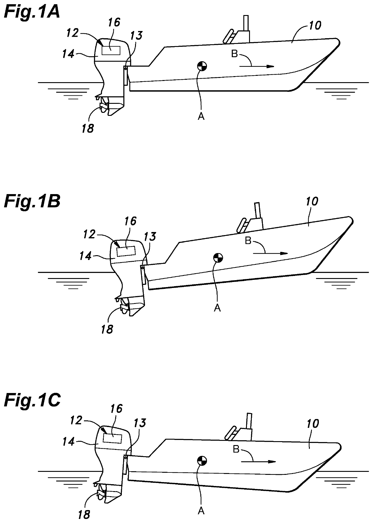
[0027]FIG. 1 shows a boat 10 fitted with an outboard motor 12 at various pitch angles. The lateral axis of this boat 10 is denoted by A, and the fore and aft axis of this boat is denoted by B. The outboard motor 12 is provided with a vertically elongated housing 14, an electric motor 16 received in an upper part of the housing 14, and a propeller 18 attached to a propeller shaft extending rearward from a lower part of the housing 14. The outboard motor 12 is attached to the boat 10 via a support shaft 13 extending laterally so that the direction of the propeller shaft of the outboard motor 12 relative to the boat 10 can be adjusted by tilting the outboard motor 12 around the support shaft 13 having an axis in parallel with the lateral axis A. This is known as trimming of the outboard motor 12.

[0028]The boat 10 is normally horizontal as shown in (A) of FIG. 1, ...


PUM


Abstract

In an outboard motor including a vertical electric motor, a cooling structure for the vertical electric motor comprises a cooling oil supply member positioned above the stator and including a plurality of outlets for dropping cooling oil on an upper surface of the stator, the outlets being arranged circumferentially in a coaxial relationship to the stator, and the outlets are configured such that an amount of cooling oil that is dropped on a part of the stator located on a first axis on a plane orthogonal to the vertical axis is smaller than an amount of cooling oil that is dropped on a part of the stator located on a second axis which is orthogonal to the first axis on the plane orthogonal to the vertical axis.

Description

TECHNICAL FIELD[0001]The present invention relates to a cooling structure for a vertical electric motor of an electric mobile body, and in particular to a cooling structure for a vertical electric motor of an outboard engine.PRIOR ART[0002]As a cooling structure for a vertical electric motor having a vertically extending rotor shaft, it is known to place a hollow annular member which is coaxial with the rotor, and has cooling oil circulating therein immediately above the rotor of the electric motor, and drip the cooling oil onto the rotor via slits provided on the bottom of the hollow annular member. See JP2020-068578A, for instance.[0003]If the electric motor is positioned precisely located at all times, the cooling oil drips onto the coils of the electric motor as designed. However, if the electric motor tilts from the vertical position, the cooling oil may fail to drop onto the coils. In such a case, the oil may flow into or drop into the air gap between the rotor and stator. Thi...

Claims


Application Information

Patent Timeline
Patent Type & Authority Applications(United States)
IPC IPC(8): H02K9/197B63H21/17
CPCH02K9/197B63H21/17H02K9/19B63H20/007B63H20/28
Inventor MIHARA, TAKAHIRO
Owner HONDA MOTOR CO LTD
Why Eureka
Try Eureka