Secondary flow suppression structure

a technology of secondary flow and suppression structure, which is applied in the direction of blade accessories, machines/engines, stators, etc., can solve the problems of reducing turbine efficiency and separation of working fluid, and achieve the effect of suppressing an increase in secondary flow

Pending Publication Date: 2022-08-18
IHI CORP
View PDF10 Cites 0 Cited by
  • Summary
  • Abstract
  • Description
  • Claims
  • Application Information

AI Technical Summary

Benefits of technology

[0012]According to the present disclosure, it is possible to provide a secondary flow suppression structure capable of suppressing an increase in secondary flow caused by a leakage in an axial turbine.

Problems solved by technology

The aforementioned leakage induces separation of the working fluid on the pressure side of the stator vane due to the impact of the leakage to a leading edge of the stator vane and the suction side in the vicinity thereof.
This increase in secondary flow results in a decrease in turbine efficiency.

Method used


Image

  • Secondary flow suppression structure
  • Secondary flow suppression structure
  • Secondary flow suppression structure

Examples


Embodiment Construction

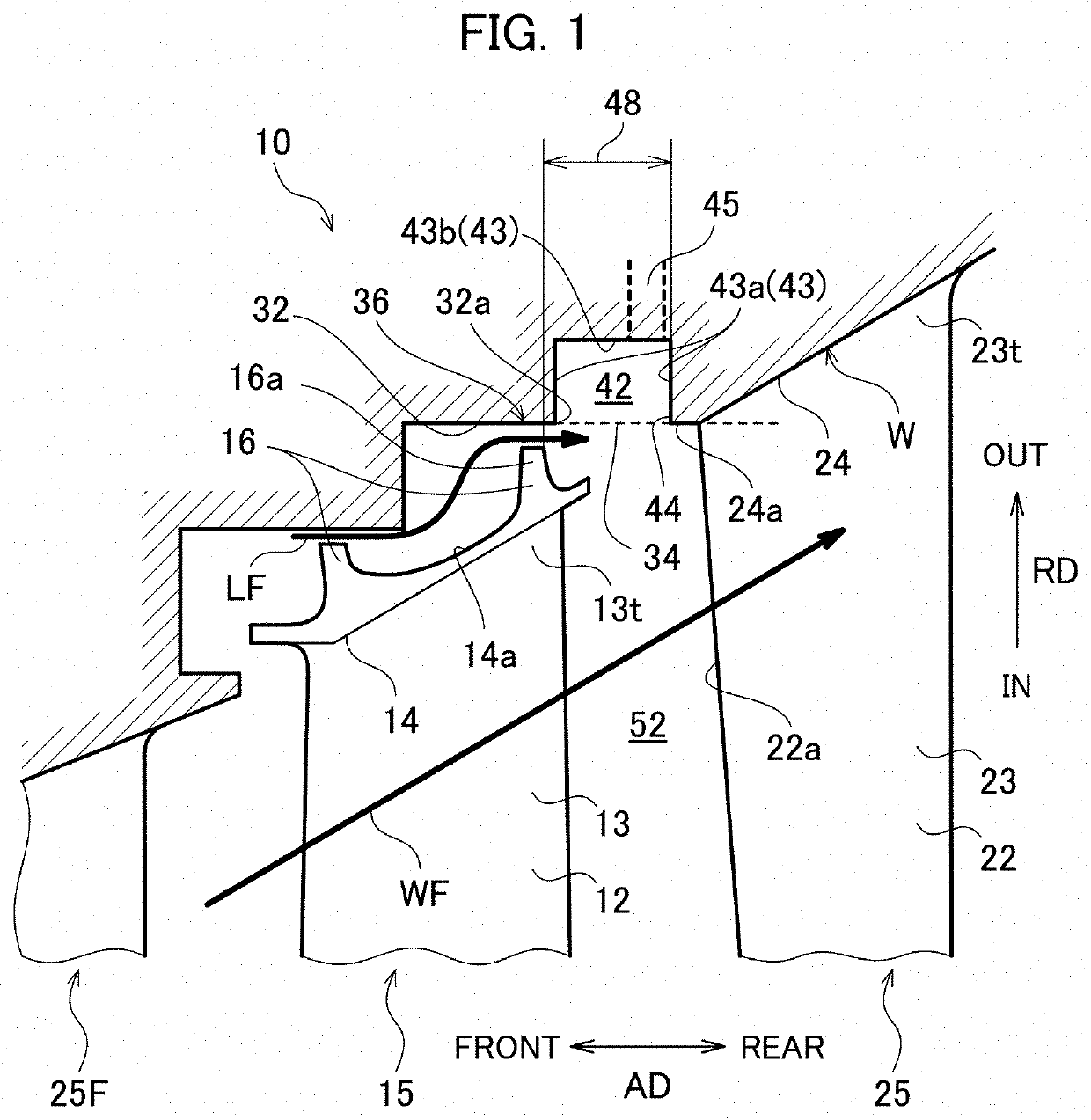
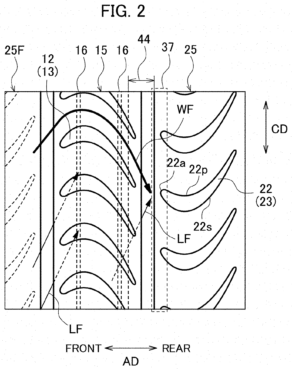
[0018]Some exemplary embodiments are described below with reference to the drawings. It should be noted that the same reference numerals are given to the common parts in the respective figures, and the redundant description thereof will be omitted. A secondary flow suppression structure 10 according to the present embodiment is applied to an axial turbine of a gas turbine engine for an aircraft or an electric generator. For convenience of explanation, an extending direction of a rotational center axis of rotor blades 12 in the axial turbine is defined as the axial direction AD. A circumferential direction CD and a radial direction RD are defined around this rotational center axis. A term “forward (front)” and a term “rearward (rear)” represent an upstream side and a downstream side of the flow of the working fluid WF, respectively.

[0019]A configuration of the secondary flow suppression structure 10 will be described. FIG. 1 is a conceptual diagram illustrating the secondary flow sup...


PUM


Abstract

A secondary flow suppression structure includes: a turbine rotor blade including an outer shroud; a turbine stator vane located rearward of the turbine rotor blade and including an outer band; a seal surface facing the outer shroud at a radial outside of the outer shroud; a fin projecting from the outer shroud toward the seal surface; and a cavity formed between the seal surface and the turbine stator vane, formed in an annular shape extending in a circumferential direction, and provided with an opening portion opening radially inward on a virtual surface of the seal surface extending rearward. A front end of the outer band is positioned at the same height as the virtual surface in a radial direction, or positioned radially inward of the virtual surface.

Description

CROSS REFERENCE TO RELATED APPLICATIONS[0001]This application is a continuation application of International Application No. PCT / JP2021 / 005338, now WO2021 / 199718, filed on Feb. 12, 2021, which claims priority to Japanese Patent Application No. 2020-060319, filed on Mar. 30, 2020, the entire contents of which are incorporated by reference herein.BACKGROUND1. Technical Field[0002]The present disclosure relates to a secondary flow suppression structure in an axial turbine.2. Description of the Related Art[0003]A gas turbine engine such as a jet engine is installed with an axial turbine to rotationally drive a compressor. The axial turbine has a plurality of rotor blades and a plurality of stator vanes. These are arranged alternately in an axial direction and constitute at least one stage. The rotor blades are arranged in a circumferential direction at predetermined intervals to constitute a blade cascade. Similarly, the stator vanes are arranged in the circumferential direction at pred...

Claims


Application Information

Patent Timeline
Patent Type & Authority Applications(United States)
IPC IPC(8): F01D11/08F01D9/02
CPCF01D11/08F01D9/02F05D2240/12F05D2220/30F05D2240/55F01D5/145F01D5/143F01D5/225
Inventor NISHII, DAISUKEHAMABE, MASAAKI
Owner IHI CORP
Why Eureka
Try Eureka