Ultrasonic motor
a technology of ultrasonic motors and motors, applied in the direction of generators/motors, electric/electrostriction/magnetostriction machines, electrical apparatus, etc., can solve the problems of repeated vibration, vibration leakage, and motor characteristics may be deteriorated, so as to enhance the stability of vibration of a stator and ensure the effect of motor characteristics
- Summary
- Abstract
- Description
- Claims
- Application Information
AI Technical Summary
Benefits of technology
Problems solved by technology
Method used
Image

Examples
second embodiment
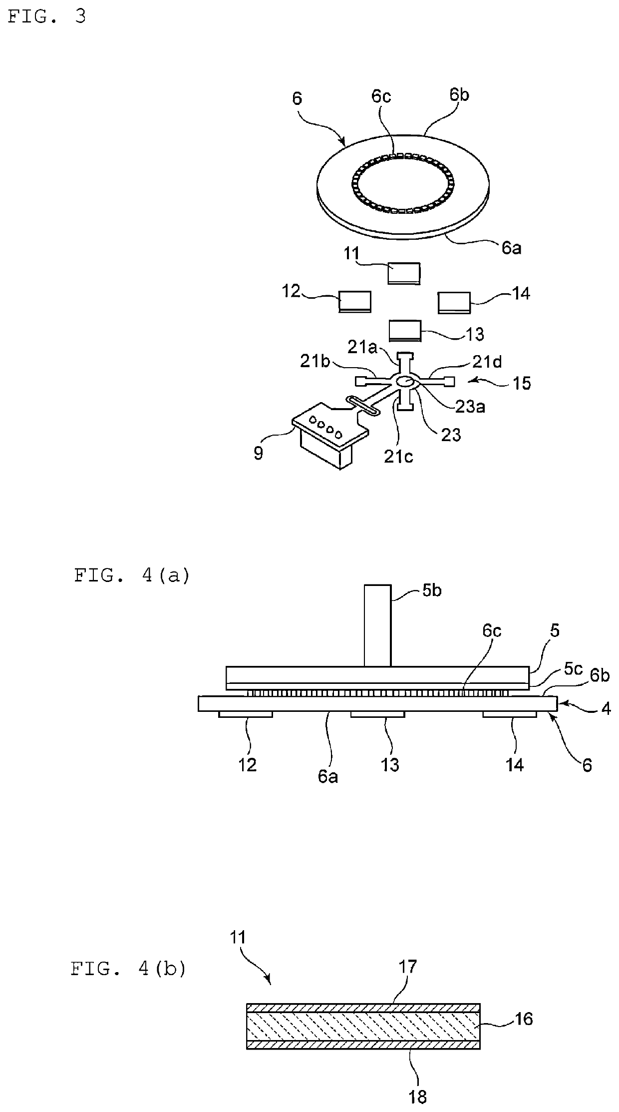
[0071]In the ultrasonic motor of the second embodiment, first to fourth detection elements 31 to 34 are provided integrally with the first to fourth piezoelectric elements 11 to 14. That is, on the outer surfaces of piezoelectric ceramic layers 16, electrodes for forming the first to fourth detection elements 31 to 34 are provided being separated from one sides of electrodes of the first to fourth piezoelectric elements 11 to 14 by gaps G. Taking the first detection element 31 as an example, the electrode for detection is an electrode 31a positioned on the outer side of a piezoelectric ceramic layer 16. A first main surface 6a side of the vibrator 6 is ground potential. A detection unit that detects vibration of the piezoelectric ceramic layer 16 between the electrode on the ground potential side and the electrode 31a is provided. The second to fourth detection elements 32 to 34 are formed similarly.
[0072]The wiring member 15 also includes signal wiring through which electric signal...
first embodiment
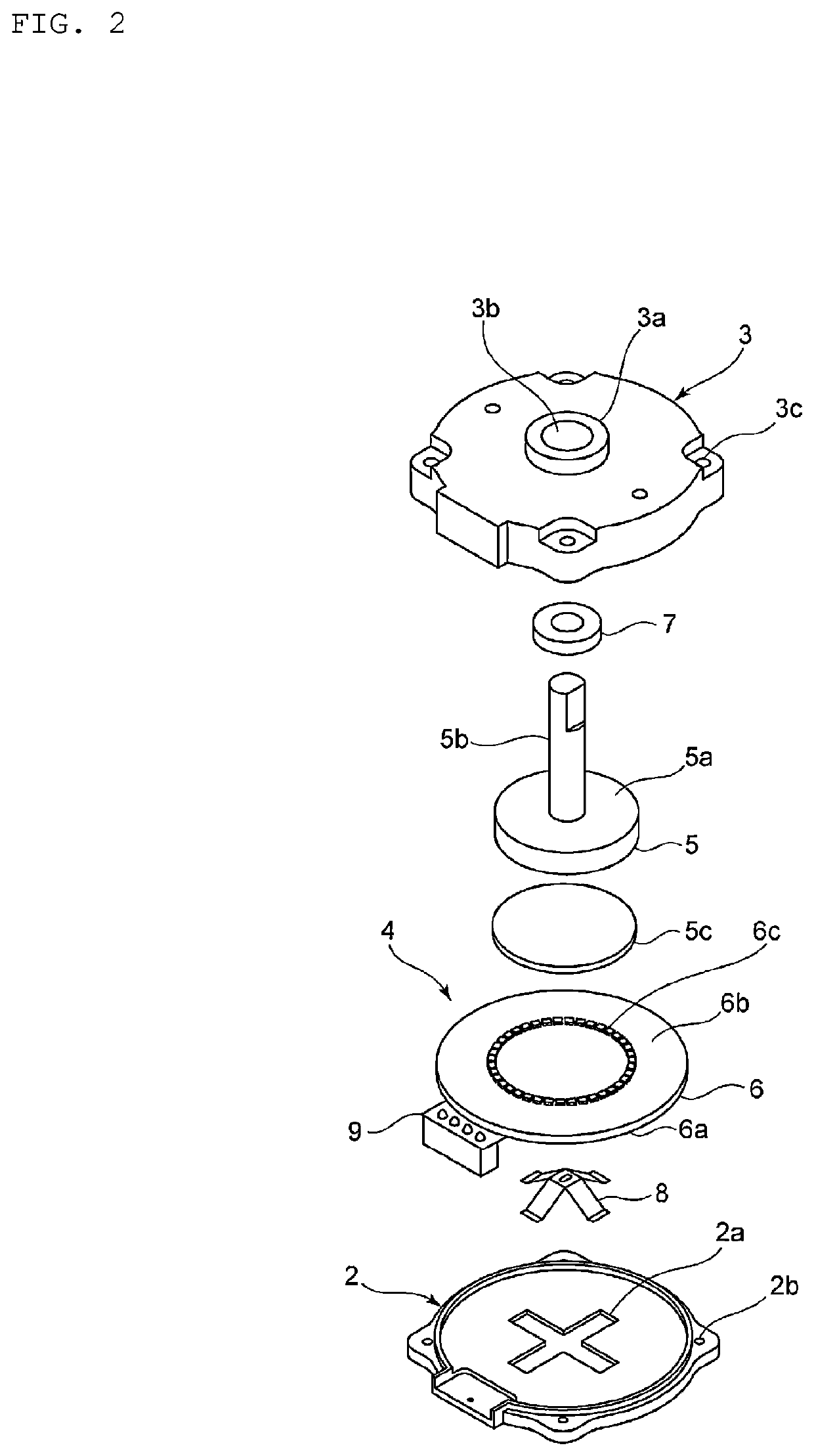
[0080]As described above, in the first embodiment illustrated in FIG. 2, the protruding portion on the rear surface of the stator 4 is fitted in the elongated hole of the pressure spring 8. Although not illustrated, the protruding portion is provided on the first main surface 6a of the vibrator 6 of the stator 4. The protruding portion has a substantially elliptical columnar shape. As a result, the elongated hole of the pressure spring 8 abuts on the protruding portion of the vibrator 6 in the rotation direction. Accordingly, positional deviation between the pressure spring 8 and the vibrator 6 due to the rotation can be effectively reduced or prevented. Hereinafter, further effect of the pressure spring 8 will be described.
[0081]FIGS. 15(a) to 15(c) are schematic front views used for describing the effect of the pressure spring.
[0082]Realistically, variation of the positional relation between the rotor body 5a and the rotating shaft 5b of the rotor 5 illustrated in FIG.15(a) can oc...
sixth embodiment
[0095]FIG. 20 is a plan view of the pressure spring according to the sixth exemplary embodiment. FIG. 21 is a plan view illustrating configurations of the pressure spring and the vibrator according to the
[0096]As illustrated in FIG. 20, the pressure spring 78 of the present embodiment is different from that of the first embodiment in the shape of a hole 78a and in that claw portions 78b are provided. Other than the above points, the configuration of the pressure spring 78 is similar to that of the pressure spring 8 of the first embodiment as described above.
[0097]As shown, a pair of the claw portions 78b is provided in parts of portions of the pressure spring 78 in contact with the hole 78a. The pair of the claw portions 78b extends toward a stator side. The pair of the claw portions 78b faces each other across the hole 78a. However, the claw portions 78b are not limited to one pair.
[0098]As illustrated in FIGS. 19 and 21, the claw portions 78b are fitted in the through hole 76c of ...
PUM
 Abstract
Description
Claims
Application Information
 - R&D
- Intellectual Property
- Life Sciences
- Materials
- Tech Scout
- Unparalleled Data Quality
- Higher Quality Content
- 60% Fewer Hallucinations
Browse by: Latest US Patents, China's latest patents, Technical Efficacy Thesaurus, Application Domain, Technology Topic, Popular Technical Reports.
© 2025 PatSnap. All rights reserved.Legal|Privacy policy|Modern Slavery Act Transparency Statement|Sitemap|About US| Contact US: help@patsnap.com