Eureka AIR delivers breakthrough ideas for toughest innovation challenges, trusted by R&D personnel around the world.

Electric rotating machine

a rotating machine and electric technology, applied in the direction of mechanical energy handling, machines/engines, mechanical equipment, etc., can solve the problems of increasing the cost of electric rotating machines, reducing the thickness of oil films locally, and reducing the purity of cooling gas, so as to suppress the effect of cooling gas purity reduction

Inactive Publication Date: 2008-02-21
HASHIBA YUTAKA +7
View PDF8 Cites 3 Cited by
  • Summary
  • Abstract
  • Description
  • Claims
  • Application Information

AI Technical Summary

Benefits of technology

[0025] A first object of the invention is to provide an electric rotating machine which comprises a shaft seal device capable of preventing contact of cooling gas and sealing oil and suppressing the reduction in purity of the cooling gas inside the machine without degassing of the sealing oil.
[0026] A second object of the invention is to provide an electric rotating machine in which a small amount of oil is sufficient for all operating conditions from startup to regular rotation and there is no excessive change in oil quantity, the electric rotating machine further comprising a highly pressure resistant brush type contact sealing device which has excellent vibration stability.
[0027] A third object of the invention is to provide an electric rotating machine, in which purity of the cooling medium in the machine is not lowered, and it is unnecessary to suction the sealing medium before feeding, the electric rotating machine comprising a low-cost shaft seal device which does not require a degassing device.
[0028] To achieve abovementioned subject matter, an electric rotating machine according the first aspect of the invention, comprises: a bearing device which rotatably supports a rotating shaft configures a rotor in a frame containing an electric rotating machine main body; a cooling medium circulating system to circulate a cooling medium within the frame to cool the electric rotating machine main body; a seal ring device which supplies a sealing medium to the outer circumferential surface side of the rotating shaft, and prevents the cooling medium from leaking to outside the frame; a sealing mechanism which is arranged to contact an outer circumferential surface of the rotating shaft, and prevents the cooling medium and the sealing medium, or the sealing medium and / or a lubricating medium inside the bearing device from contacting the outside air.
[0031] To achieve abovementioned subject matter, an electric rotating machine according the fourth aspect of the invention, comprises: a bearing device which rotatably supports a rotating shaft configuring a rotor inside a frame which contains an electric rotating machine main body; a lubricating medium circulating system to circulate a lubricating medium in the bearing device; a cooling medium circulating system to circulate a cooling medium within the frame to cooling the electric rotating machine main body; an oil deflector which is disposed on the outer circumferential surface of the rotating shaft which is on the inner side and / or the outer side of the frame of the bearing device and prevents a lubricant that is supplied to the bearing device from flowing inside the frame or from flowing outside the frame; a seal ring device which is disposed inside the frame further toward inside the machine than the bearing device, supplies a sealing medium to the outer circumferential surface side of the rotating shaft, and prevents the cooling medium from leaking to the outer side of the frame; and a sealing mechanism which is formed of a brush seal to contact the outer circumferential surface of the rotating shaft, and prevents the sealing medium and the lubricating medium from contacting each other.
[0033] To achieve abovementioned subject matter, an electric rotating machine according the sixth aspect of the invention, comprises: a bearing device which rotatably supports a rotating shaft configuring a rotor inside a frame which contains an electric rotating machine main body; a lubricating medium circulating system to circulate a lubricating medium in the bearing device; a cooling medium circulating system to circulate a cooling medium within the frame to cool the electric rotating machine main body; an oil deflector which is disposed on the outer circumferential surface of the rotating shaft which is on the inner side and / or the outer side of the frame of the bearing device, and prevents a lubricant that is supplied to the bearing device from flowing inside the frame from flowing outside the frame; a seal ring device which is disposed inside the frame further toward the inner frame than the bearing device, and supplies sealing medium to the outer circumferential surface side of the rotating shaft and prevents the cooling medium from leaking to the outer side of the frame; and a sealing mechanism which is inside the frame of the bearing device, is formed of a brush seal to contact the outer circumferential surface of the rotating shaft, prevents the cooling medium and the lubricating medium in the bearing device from contacting each other and prevents the cooling medium from leaking to outer side of the machine.

Problems solved by technology

However, the suction processing device 58 is of a comparatively high cost, and this is one factor causing increased cost for the electric rotating machine in which hydrogen gas or the like is used as the cooling medium.
Furthermore, the thickness of the oil film decreases locally due to deformation, and vibration is caused by the frictional force of that portion.
However, in a liquid seal for high pressure difference using a liquid as the sealing medium (purge oil), such as in a gas sealing inside the turbine generator, sufficient sealing properties can not be obtained, and further, a large amount of sealing oil is necessary.
However, there is no description of any measures for dealing with possible dropping of the brush seal due to the pressure of the leaking oil.
Thus, both types are not necessarily provided at the bearing side surface.
However, the brush seal that uses this special kind of brush is attached to a machine having a pressure difference between the inside and the outside the machine, and it clearly different from one that basically does not seal a pressure difference.

Method used


Image

  • Electric rotating machine
  • Electric rotating machine
  • Electric rotating machine

Examples


first embodiment

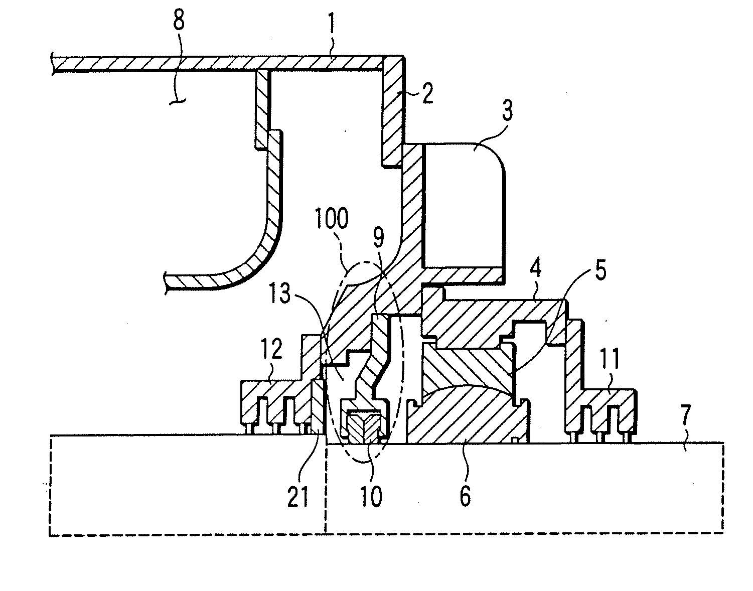
[0066] Now, embodiments of an electric rotating machine including a shaft seal device according to the invention will be explained with reference to the drawings. FIG. 1 is an axial direction cross-sectional view of an area around a shaft seal device of an electric rotating machine showing the invention, and it differs from FIG. 28 which shows the prior art described above, in that a brush seal 21 serving as a sealing mechanism which does not require a lubricating member formed of a seal brush is provided at a seal cavity 13 of an internal oil deflector 12. In other words, in this embodiment, a shaft seal device 100 is formed of a seal ring 10 mounted inside a seal casing 9 and the brush seal 21 mounted on the internal oil deflector 12.

[0067] In the thus configured shaft seal device 100 of the electric rotating machine according to the first embodiment, a hydrogen gas 8 which is used as a cooling medium inside the machine attempts to enter the seal cavity 13 from the gap between the...

second embodiment

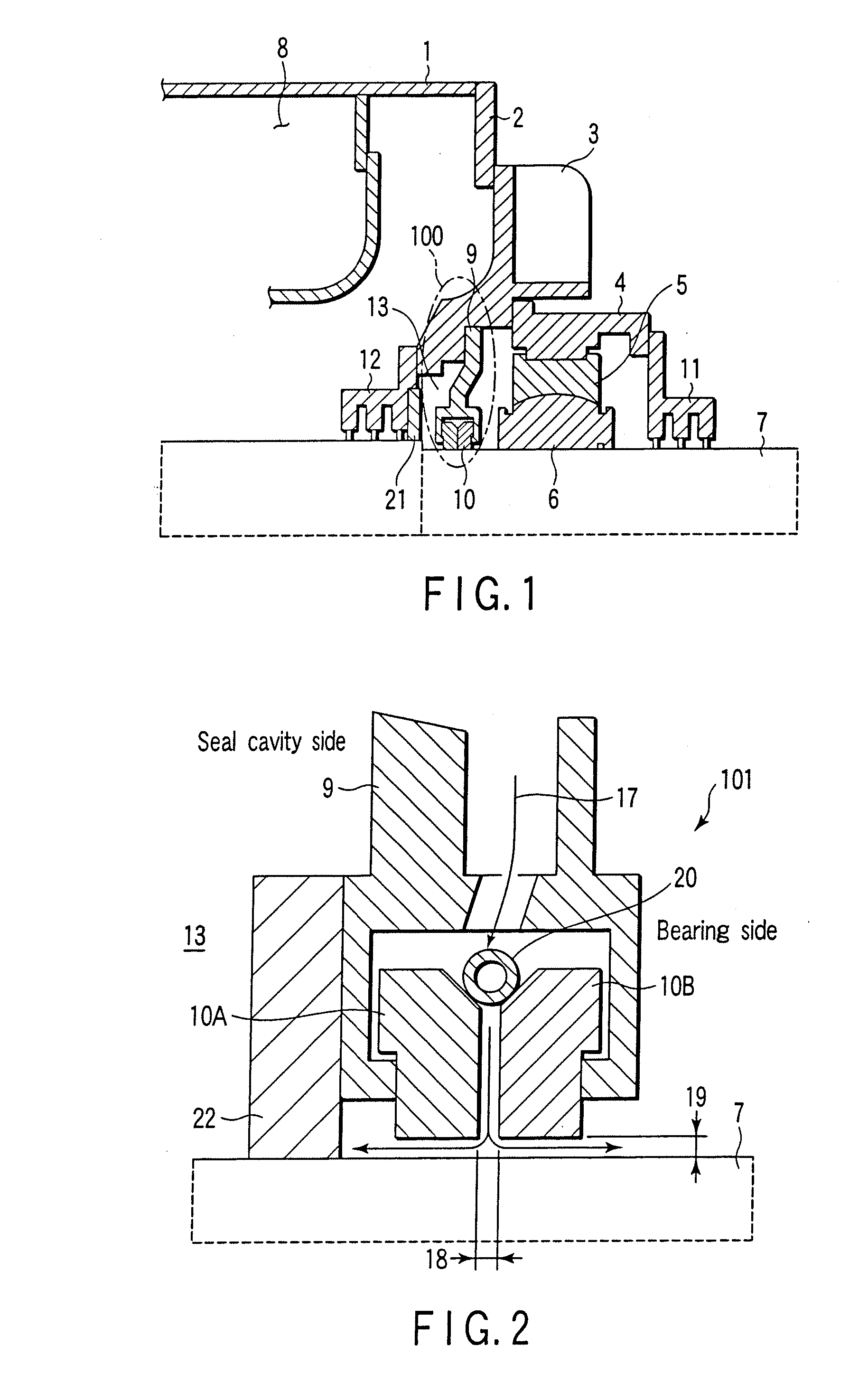
[0070] Next, the shaft seal device of the electric rotating machine of the invention will be described with reference to FIG. 2. That is, a structure is provided in which a brush seal 22 which is a sealing mechanism is mounted at the seal cavity 13 side of the seal casing 9 which holds seal rings 10A and 10B which are the same as that of the prior art is mounted.

[0071] In a shaft seal device 101 of the second embodiment having this configuration, the sealing oil is caused to flow from an axial direction gap 18 of the seal ring 10A at the seal cavity side and the seal ring 10B at the bearing side to narrow gaps 19 between the seal ring 10A and rotating shaft 7, and between the seal ring 10B and the rotating shaft 7, respectively, and then caused to flow out to the seal cavity side and the bearing side, respectively. However, because the brush seal 22 is provided at the seal cavity 13 side, the sealing oil 17 which flows out to the seal cavity 13 side never flows out to the seal cavit...

third embodiment

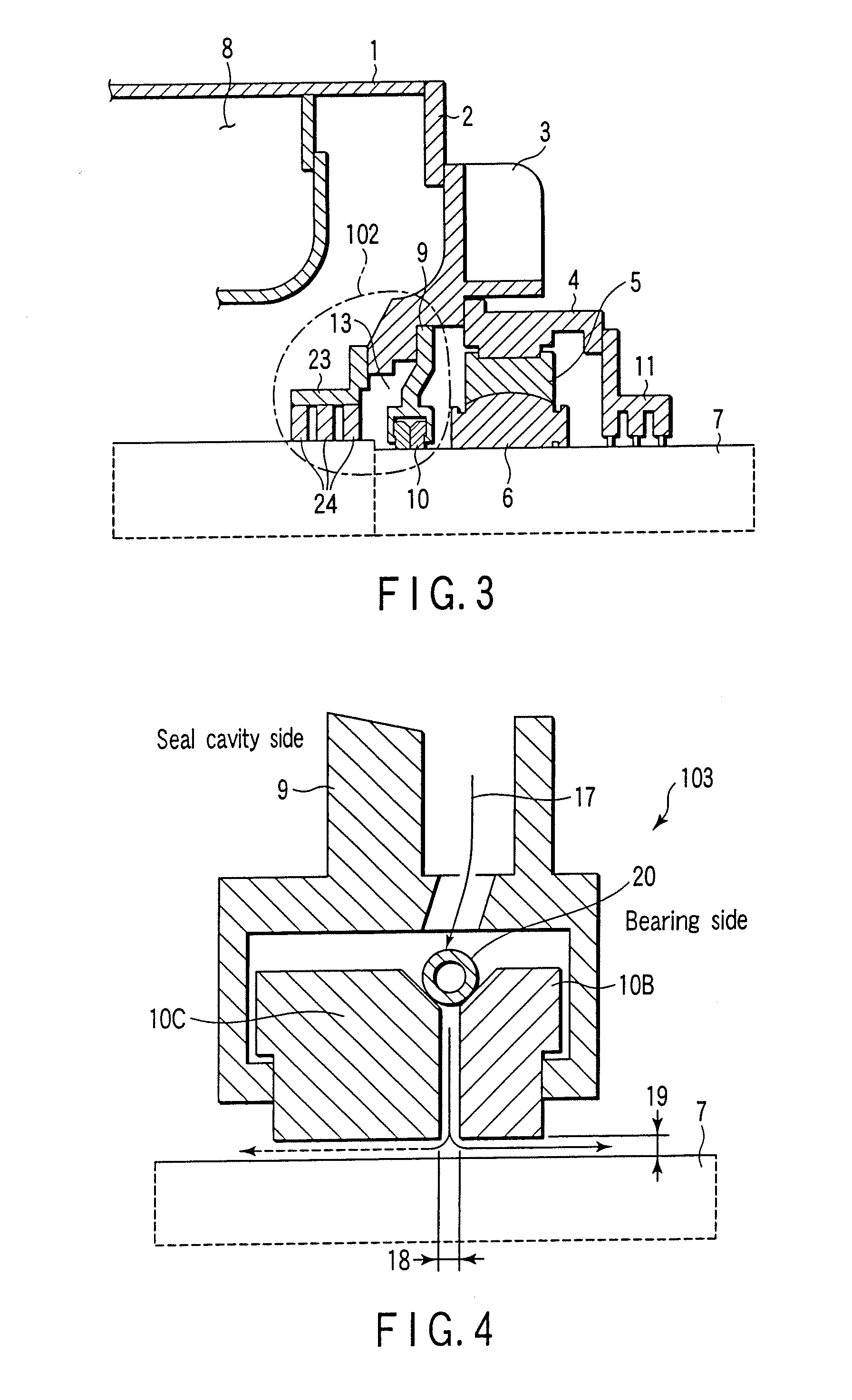
[0073] Next, the shaft seal device of the electric rotating machine of the invention will be described with reference to FIG. 3. In this embodiment, the internal oil deflector 12 of FIG. 28 is not provided, and a sealing mechanism which does not require a lubricating member, e.g., a seal brush 24, is supported by a brush seal holder 23 and is mounted to an end bracket 3 at this portion. The brush seal 24 is provided with multiple stages in the axial direction (3 stages in FIG. 3). A shaft seal device 102 is configured by the brush seal 24 and the seal ring 10 which is mounted on the seal casing 9.

[0074] In the third embodiment as configured above, the hydrogen gas 8 which is use as the cooling gas inside the machine is hindered from entering the seal cavity 13 by the brush seal 24. In addition, the sealing oil 17 which flows out from the gap between the seal ring 10 and the rotating shaft 7 is hindered from going out from the seal cavity 13 to inside the machine by the brush 24 in t...


PUM


Abstract

Hydrogen gas is circulated to cool an electric rotating machine main body, and brush seals are provided to contact a predetermined position on the outer circumferential surface of a rotating shaft. As a result, contact of a sealing oil and the hydrogen gas, contact of a lubricating oil and the sealing oil in the bearing, and leakage of the hydrogen gas outside the machine are prevented.

Description

CROSS-REFERENCE TO RELATED APPLICATIONS [0001] This present application is a Divisional Application of application Ser. No. 11 / 128,368 filed May 13, 2005, which is a Continuation Application of PCT Application No. PCT / JP03 / 14481, filed Nov. 13, 2003, which was published under PCT Article 21(2) in Japanese. [0002] This application is based upon and claims the benefit of priority from prior Japanese Patent Applications No. 2002-329168, filed Nov. 13, 2002; and No. 2003-058273, filed Mar. 5, 2003, the entire contents of both of which are incorporated herein by reference.BACKGROUND OF THE INVENTION [0003] 1. Field of the Invention [0004] The present invention relates to an electric rotating machine comprising a shaft seal device which cools an electric rotating machine main body with a cooling medium such as hydrogen gas and which seals a shaft through portion. [0005] 2. Description of the Related Art [0006] In a large capacity turbine generator, for example, pressurized hydrogen gas is...

Claims


Application Information

Patent Timeline
Patent Type & Authority Applications(United States)
IPC IPC(8): F16J15/44F16J15/26F16J15/32H02K5/10H02K5/124H02K5/16H02K7/08H02K9/00H02K9/10H02K9/19H02K9/20
CPCF16J15/26F16J15/3288F16J15/441F16J15/442H02K9/20H02K5/124H02K5/1672H02K9/10H02K9/19F16J15/443H02K9/197
Inventor HASHIBA, YUTAKAMIKAMI, MAKOTOHAYASHI, TAKESHIKAZAO, YUKIHIKOSAITO, IKUOSHIOMI, HIDEKAZUTANIYAMA, YOSHIHIROKABATA, YASUO
Owner HASHIBA YUTAKA
Why Eureka
Eureka Blog
Learn More