
MEMS structure

A substrate and piezoelectric composite technology, applied in the field of MEMS structure, can solve the problem of low sensitivity of MEMS structure

Pending Publication Date: 2020-01-10
ANHUI ORINFIN ACOUSTIC SCI&TECH CO LTD
View PDF0 Cites 2 Cited by
  • Summary
  • Abstract
  • Description
  • Claims
  • Application Information

AI Technical Summary

Problems solved by technology

[0004] Aiming at the problem of low sensitivity of the MEMS structure in the related art, this application proposes a MEMS structure, which can improve the sensitivity of the MEMS structure

Method used


Image

  • MEMS structure
  • MEMS structure
  • MEMS structure

Examples


Embodiment Construction

[0029] The following will clearly and completely describe the technical solutions in the embodiments of the application with reference to the drawings in the embodiments of the application. Apparently, the described embodiments are only some of the embodiments of the application, not all of them. All other embodiments obtained by persons of ordinary skill in the art based on the embodiments in this application belong to the protection scope of this application.

[0030] The following disclosure provides many different embodiments or examples for implementing the different features of the present application. Specific examples of components and arrangements are described below to simplify the present application. These are of course examples only and are not intended to be limiting. For example, the dimensions of the elements are not limited to the disclosed ranges or values, but may depend on process conditions and / or desired properties of the device. In addition, in the fol...


PUM


Abstract

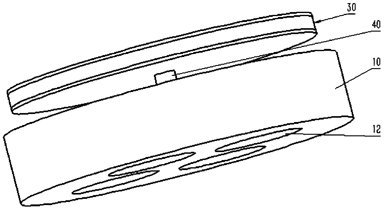
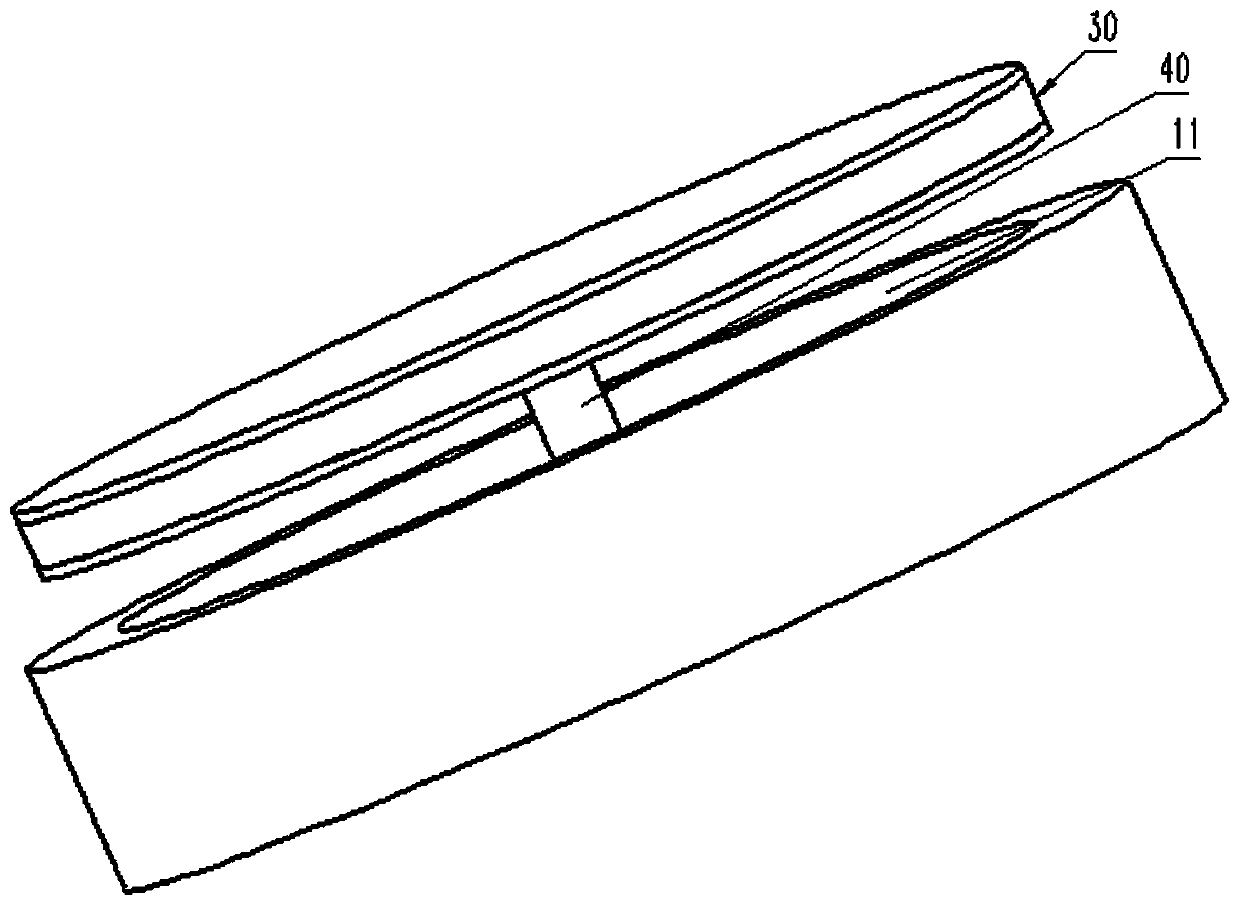
The invention discloses an MEMS structure, which comprises a substrate having a cavity and a pillar located in the cavity; a piezoelectric composite vibration layer which is formed over the cavity, the first end of the supporting column is connected with the substrate, and the second end of the supporting column supports the piezoelectric composite vibration layer. According to the MEMS structure,the piezoelectric composite vibration layer is supported by the supporting columns, so that the sensitivity of the MEMS structure is improved.

Description

technical field [0001] The present application relates to the field of semiconductor technology, and in particular, relates to a MEMS (short for MicroelectroMechanical Systems, microelectromechanical systems) structure. Background technique [0002] MEMS microphones (microphones) mainly include two types: capacitive and piezoelectric. MEMS piezoelectric microphone is a microphone prepared by microelectromechanical system technology and piezoelectric thin film technology. Due to the use of semiconductor planar technology and bulk silicon processing technology, it has small size, small volume and good consistency. At the same time, compared with condenser microphones, there are advantages such as no need for bias voltage, wide operating temperature range, dustproof, waterproof, etc., but its sensitivity is relatively low, which restricts the development of MEMS piezoelectric microphones. [0003] For the problem of how to improve the sensitivity of the piezoelectric MEMS stru...

Claims


Application Information

Patent Timeline
IPC IPC(8): H04R19/04
CPCH04R19/04H04R2201/003
Inventor 刘端
Owner ANHUI ORINFIN ACOUSTIC SCI&TECH CO LTD
Learn More