Supercharge Your Innovation With Domain-Expert AI Agents!

Enhanced recoater edges

a technology of recoater edges and edges, applied in the field of enhanced recoater edges, can solve the problems of build failure, recoat quality may begin to fail,

Active Publication Date: 2022-08-25
HAMILTON SUNDSTRAND CORP
View PDF3 Cites 0 Cited by
  • Summary
  • Abstract
  • Description
  • Claims
  • Application Information

AI Technical Summary

Benefits of technology

This solution significantly reduces build failures and maintains consistent build quality by continuously replacing the recoater blade with fresh material, preventing clumps and ensuring uninterrupted additive manufacturing processes.

Problems solved by technology

As a recoater blade degrades due to friction, the recoating quality may begin to fail.
These issues can cause build failures.

Method used


Image

  • Enhanced recoater edges
  • Enhanced recoater edges

Examples


Embodiment Construction

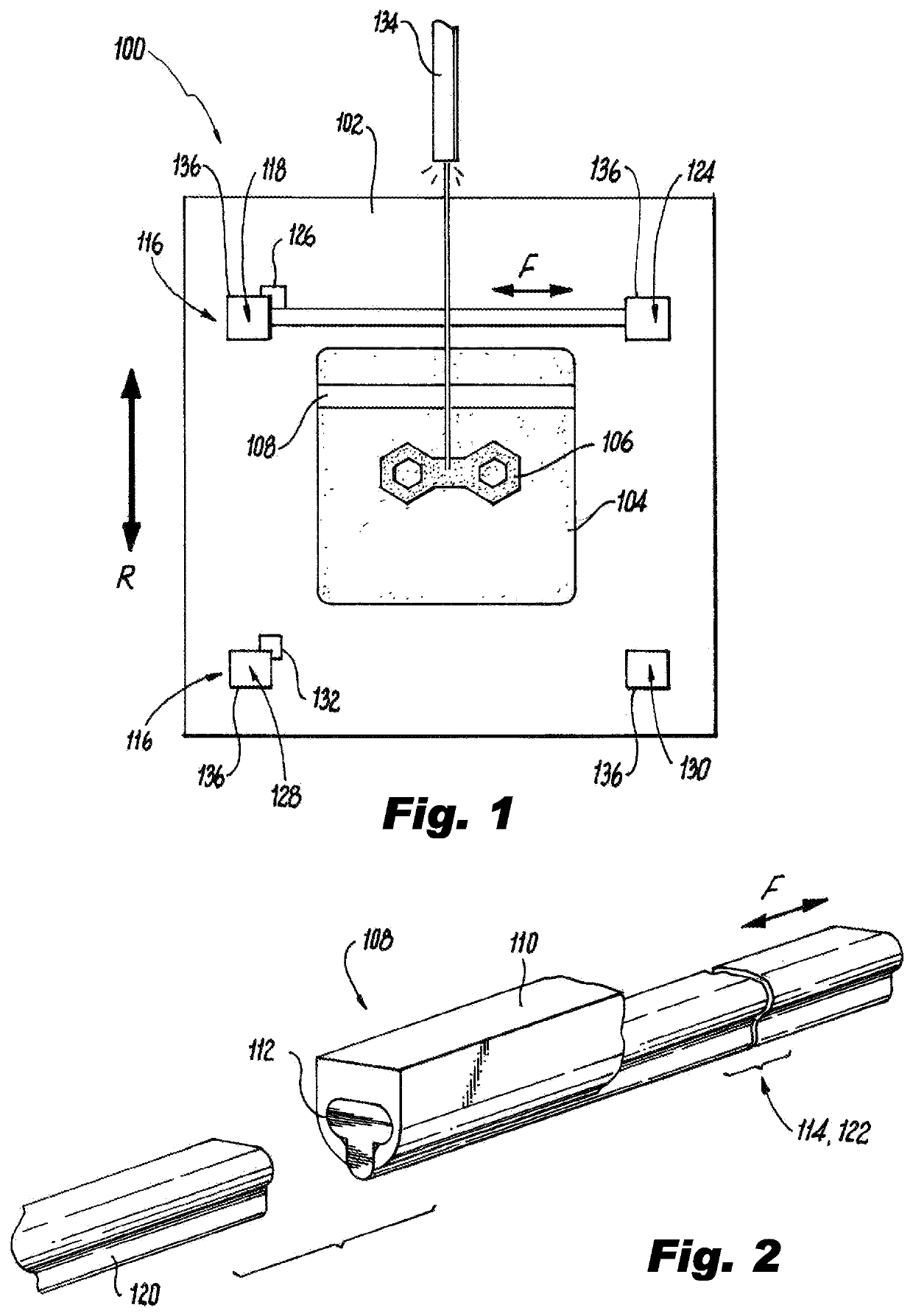
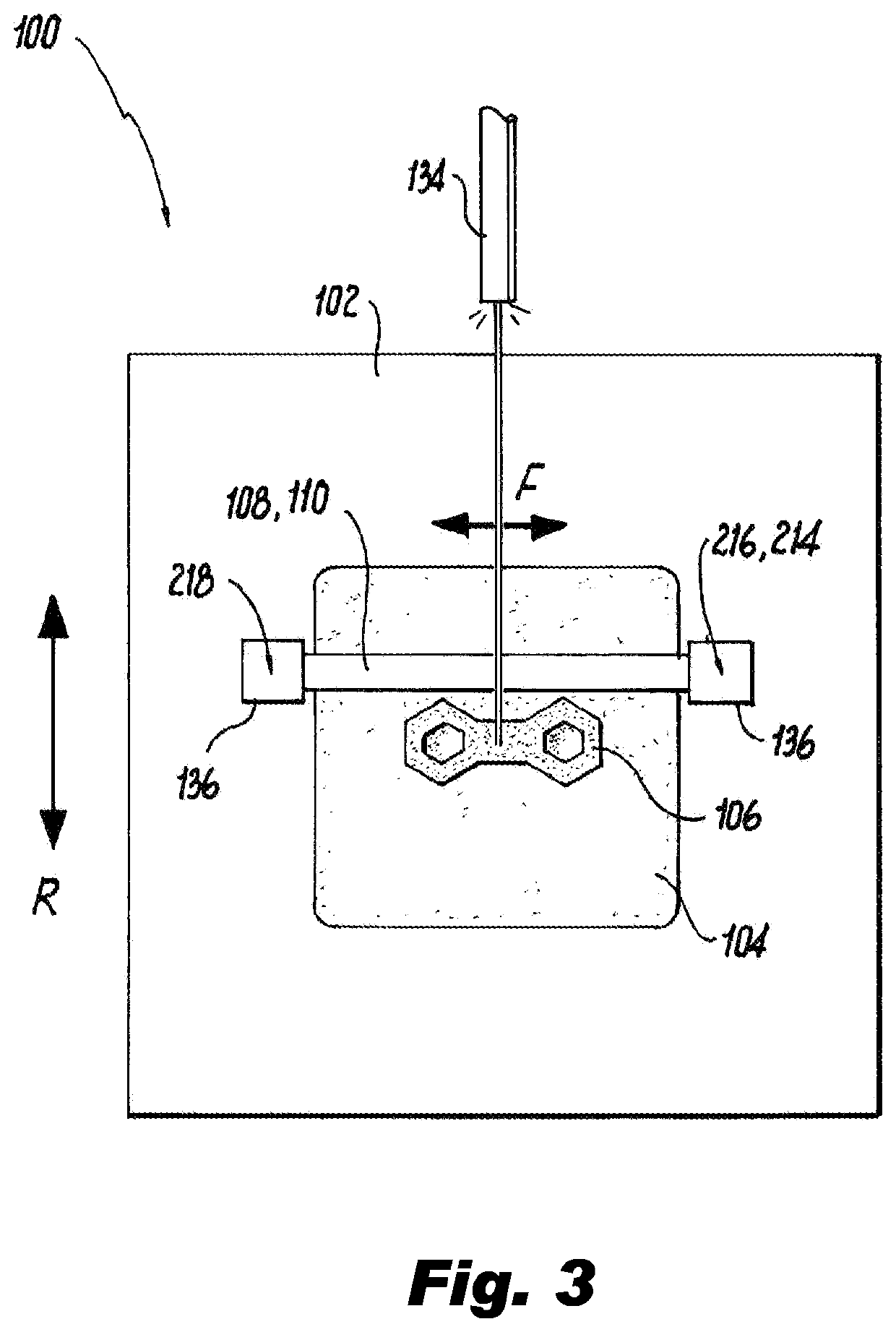
[0019]Reference will now be made to the drawings wherein like reference numerals identify similar structural features or aspects of the subject disclosure. For purposes of explanation and illustration, and not limitation, a partial view of an exemplary embodiment of an additive manufacturing device in accordance with the disclosure is shown in FIG. 1 and is designated generally by reference character 100. Other embodiments of additive manufacturing devices in accordance with the disclosure, or aspects thereof, are provided in FIGS. 2-3, as will be described. The systems and methods described herein can be used to improve build quality in additive manufacturing processes such as laser powder bed fusion (LPBF).

[0020]The additive manufacturing device 100 includes a build platform 102 a portion of which is a build area 104 for additively manufacturing a part 106. A recoater 108 is operatively connected to the build platform 102 to move relative to the build platform 102 to coat unfused ...


PUM


Abstract

An additive manufacturing device includes a build platform. A recoater is operatively connected to the build platform to move relative to the build platform to coat unfused powder onto a build on the build platform. The recoater includes a recoater mount defining a length-wise receptacle therein, and a recoater blade seated in the receptacle. A blade reel system is operatively connected to the recoater to replace the recoater blade in the receptacle during a build on the build platform.

Description

CROSS-REFERENCE TO RELATED APPLICATIONS[0001]This is a continuation of U.S. patent application Ser. No. 16 / 258,121 filed Jan. 25, 2019 the content of which is incorporated by reference herein in its entirety.BACKGROUND1. Technological Field[0002]The present disclosure relates to additive manufacturing, and more particularly to controlling geometries in additive manufacturing techniques such as laser powder bed fusion, and the like.2. Description of Related Art[0003]Laser powder bed fusion additive manufacturing and electron beam additive manufacturing use directed energy in conjunction with powder feedstock to form a sintered structure. The energy source, e.g., the laser beam or electron beam, excites the target material to the point of phase-change. This melt-pool process, coupled with an active toolpath effectively welds a single layer of powder feedstock into a solid state. Once one layer has been formed, a recoater pushes a thin layer of powder feedstock across the build surface...

Claims


Application Information

Patent Timeline
Patent Type & Authority Applications(United States)
IPC IPC(8): B29C64/153B22F10/20
CPCB29C64/153B22F10/20B33Y10/00B33Y40/00B33Y30/00B29C64/214B29C64/321Y02P10/25B22F10/28B22F12/67B33Y50/02B29C64/386B29C64/20B23K26/06B29K2105/251G05B19/41805G05B2219/49
Inventor BINEK, LAWRENCEMORGANSON, DAVID W.
Owner HAMILTON SUNDSTRAND CORP
Features
  • R&D
  • Intellectual Property
  • Life Sciences
  • Materials
  • Tech Scout
  • Unparalleled Data Quality
  • Higher Quality Content
  • 60% Fewer Hallucinations
Learn More