
Gas-filling device

a gas-filling device and gas-filling technology, which is applied in the direction of positive displacement liquid engines, machine/engines, vehicle maintenance, etc., can solve the problems of losing the original use function, poor overall strength of the gas-filling device's air chamber, and users' inability to effectively infla

Inactive Publication Date: 2022-08-25
LIANG SHENGWEI
View PDF11 Cites 0 Cited by
  • Summary
  • Abstract
  • Description
  • Claims
  • Application Information

AI Technical Summary

Benefits of technology

The present invention provides a new type of Gas-filling device that is practical, easy to operate, accurately measures air pressure, is stable, durable, safe, can be easily disassembled and assembled, and is easy to carry and store while being cost-effective.

Problems solved by technology

However, the traditional Gas-filling device has the following shortcomings during use: 1. Gas-filling devices such as the barometers of ordinary pumps on the market are easy to break and the air pressure measurement is inaccurate; 2. The handle of the Gas-filling device is difficult to inflate the device to be gas-filled during use, and the handle of the Gas-filling device has a poor touch and laborious use, easy to slip, it is difficult for users to effectively inflate; 3. The pedal position of common Gas-filling devices on the market is easy to break; 4. On account of the air pressure in the air chamber is higher than that outside the air chamber, and the device is squeezed in use, the pressure in the air chamber increases, making the air in the air chamber easily escape from the end cover or the end cover is deformed to produce air leakage, which affects the use; 5. Traditional Gas-filling devices are inconvenient to carry and store; 6. The base is unstable during air inflation, and the overall strength of the Gas-filling device's air chamber is poor.
In case of the air chamber leaks due to scratches, abrasion, or dazzling, the device will quickly lose its original form, thereby losing its original use function, and even dangerous; 7. At the interface of the air tube, the connection operation is not convenient.

Method used


Image

  • Gas-filling device
  • Gas-filling device
  • Gas-filling device

Examples


Embodiment Construction

[0023]The technical solutions of this present invention will be described in further detail below in conjunction with specific implementations. The technical features or connection relationships of the present invention that are not described in detail are all the existing technologies applied. The present invention will be further described in detail below with reference to the accompanying drawings.

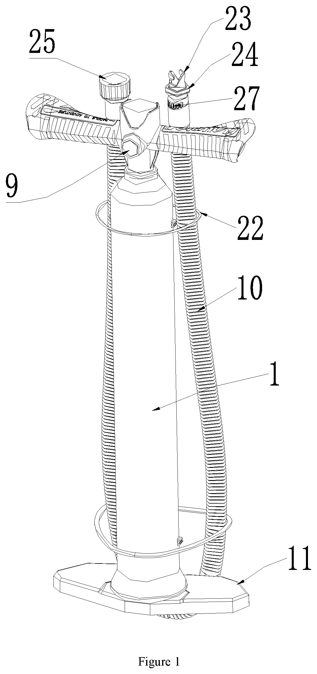
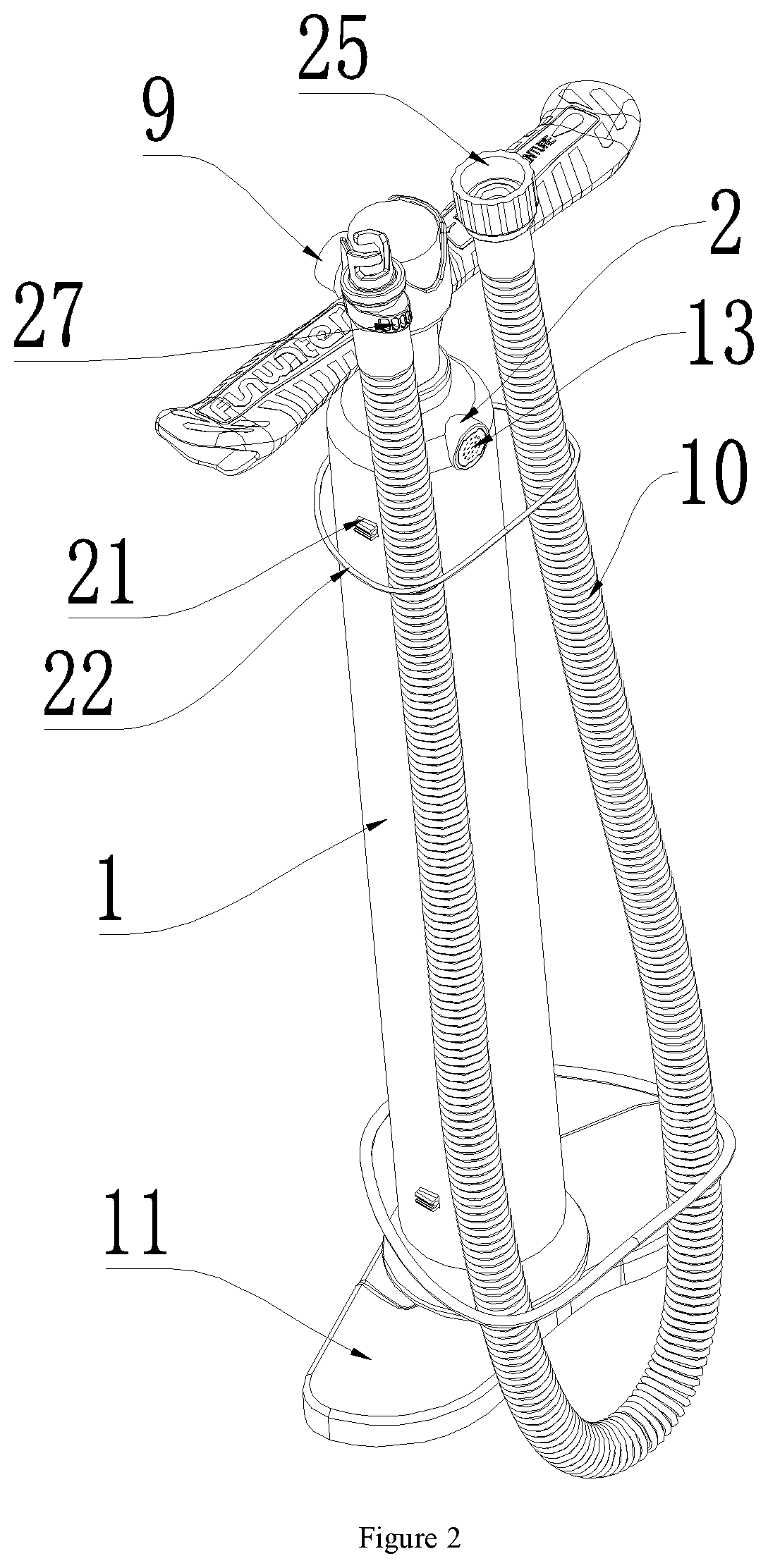
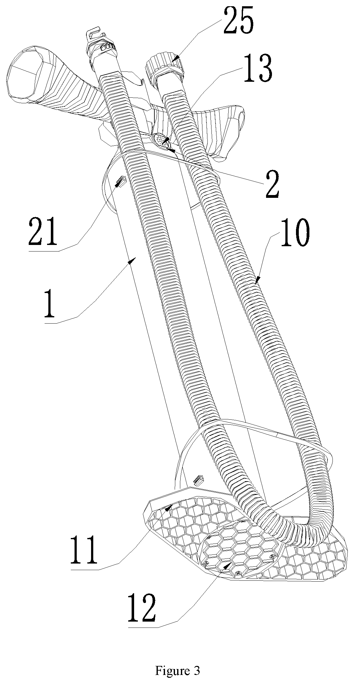
[0024]As shown in FIGS. 1-8, the new type of Gas-filling device of the present invention includes a support tube 1 with hollow tubular structure. The upper side wall of the said support tube 1 is provided with air inlet 2, and the support tube 1 is provided with an integrated pressure measuring piston 3 sliding along the central axis of the support tube 1. The integrated pressure measuring piston 3 includes one-way valve piston body 4, hollow cylinder 5, buffer chamber 6, barometer 7 and anti-skid handle 8 that are sealed connection in sequence from bottom to top, and the side wall of t...


PUM


Abstract

The utility model relates to a new type of Gas-filling device, which includes a support tube with hollow tubular structure. The upper side wall of the said support tube is provided with air inlet, and the support tube is provided with an integrated pressure measuring piston sliding along the central axis of the support tube. The integrated pressure measuring piston includes one-way valve piston body, hollow cylinder, buffer chamber, barometer and anti-skid handle that are sealed connection in sequence from bottom to top, and the side wall of the said buffer chamber is provided with air outlet, the side wall of the support tube is provided with air outlet hose which is matched and sealed in threaded connection with the air outlet, and honeycomb base is provided under the support tube, and an end cover is sealed and provided on the honeycomb base. The invention belongs to the technical field of Gas-filling devices, and specifically provides a new type of Gas-filling device appropriate for production and life with high practicability, simple operation, accurate air pressure measurement, good stability, durability, high safety factor, convenient dis-assembly and assembly, convenient carrying and storage, and low cost.

Description

TECHNICAL FIELD[0001]The invention belongs to the technical field of Gas-filling devices, and specifically refers to a new type of Gas-filling device.BACKGROUND ART[0002]The Gas-filling device is a product that people often use in production or daily life. The traditional Gas-filling device is a structure with one air chamber and one air nozzle, and there is an internal or external plug in the air nozzle to seal the chamber air. However, the traditional Gas-filling device has the following shortcomings during use: 1. Gas-filling devices such as the barometers of ordinary pumps on the market are easy to break and the air pressure measurement is inaccurate; 2. The handle of the Gas-filling device is difficult to inflate the device to be gas-filled during use, and the handle of the Gas-filling device has a poor touch and laborious use, easy to slip, it is difficult for users to effectively inflate; 3. The pedal position of common Gas-filling devices on the market is easy to break; 4. O...

Claims


Application Information

Patent Timeline
IPC IPC(8): F04B33/00B60S5/04F04B39/10F04B39/00
CPCF04B33/00B60S5/04F04B39/10F04B39/0005F04B39/0016F04B39/123
Inventor LIANG, SHENGWEI
Owner LIANG SHENGWEI
Learn More