Unlock instant, AI-driven research and patent intelligence for your innovation.

Radio frequency auto-transformer, radio frequency device and method of construction of an auto-transformer

a radio frequency and auto-transformer technology, applied in the direction of transformers, fixed transformers, semiconductor/solid-state device details, etc., can solve the problems of limited impedance transformation capability vs bandwidth, and the disadvantage of not providing electrical isolation between primary and secondary circuits

Pending Publication Date: 2022-09-08
NXP BV
View PDF0 Cites 0 Cited by
  • Summary
  • Abstract
  • Description
  • Claims
  • Application Information

AI Technical Summary

Benefits of technology

The present invention provides an automatic transformer circuit, a radio frequency device, and a method for creating an RF automatic transformer. The specific details of the invention are presented in the accompanying claims. These and other aspects of the invention will be explained in more detail below.

Problems solved by technology

Since part of the winding performs a ‘double duty’ function, autotransformers have the advantages of often being smaller, lighter, and cheaper than typical dual-winding transformers, whilst incurring a disadvantage of not providing electrical isolation between primary and secondary circuits.
U.S. Pat. No. 9,087,838 describes a structure and method for a high-k transformer that specifically only uses two capacitive and two inductive coupling paths in total, and therefore suffers from a limited impedance transformation capability vs bandwidth due to it being a regular transformer type.

Method used


Image

  • Radio frequency auto-transformer, radio frequency device and method of construction of an auto-transformer
  • Radio frequency auto-transformer, radio frequency device and method of construction of an auto-transformer
  • Radio frequency auto-transformer, radio frequency device and method of construction of an auto-transformer

Examples


Embodiment Construction

[0019]Examples of the present invention introduce an inductive and capacitive coupling enhancement technique, both in terms of schematic and layout implementation that provides a coupling-enhanced auto-transformer that achieves a wide-band, low-insertion loss performance. In some examples, the coupling-enhanced auto-transformer may be used in a PA OMN. In some examples, the embodiments described herein may be particularly useful for a wide-band, high-linearity and high-efficiency PA design.

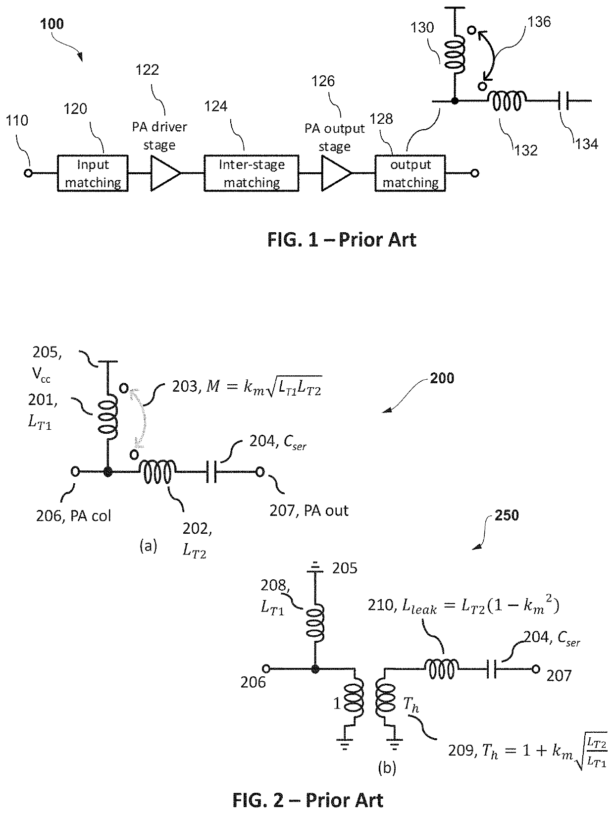
[0020]Briefly referring back to the known auto-transformer design 200 and model 250 in FIG. 2, the inventors have recognized and appreciated that, for the same impedance transformation ratio, increasingly the inductive coupling km can decrease the leakage inductance of LT2, which effectively reduces the effect of the parasitic resistance of the LT2 and improves the insertion loss. Thus, the inventors have recognized and appreciated that increasing the inductive coupling km can effectively improve ...


PUM

PropertyMeasurementUnit
impedanceaaaaaaaaaa
depthaaaaaaaaaa
depthaaaaaaaaaa

Abstract

A radio frequency, RF, auto-transformer circuit (300, 700, 901) and method (1000) of constructing a RF auto-transformer are described. The RF, auto-transformer circuit (300, 700, 901) includes: an inner coil formed (1102) with a first metal layer (MT1) to create a first shunt inductor (302), wherein at least a portion of the inner coil is overlayed (1106) with a second metal layer (MT2) that creates a first series inductor (303) that exhibits inductive coupling to the first shunt inductor (302). An outer coil is formed (1104) with the first metal layer (MT1) that creates a second series inductor (304), where the outer coil is located adjacent the inner coil and provides inductive coupling between the second series inductor (304) and each of the first shunt inductor (302) and first series inductor (303). At least a portion of the outer coil is overlayed (1008) with the second metal layer (MT2) that creates a second shunt inductor (301) that exhibits inductive coupling between the second shunt inductor (301) and each of the first shunt inductor (302) and first series inductor (303) and second series inductor (304). The outer coil is connected (1112) to the inner coil using vias and the respective first metal layer (MT1) is connected to the second layer (MT2) using vias.

Description

FIELD OF THE INVENTION[0001]The field of the invention relates to an auto-transformer, a radio frequency device having an auto-transformer and a method of construction of an auto-transformer. The invention is applicable to, but not limited to, a radio frequency coupling-enhanced auto-transformer circuit and layout.BACKGROUND OF THE INVENTION[0002]An auto-transformer is a single winding transformer that works on the principle of Faraday's Law of electromagnetic induction, and is primarily used in a low voltage range, for industrial, commercial and laboratory purposes. Since part of the winding performs a ‘double duty’ function, autotransformers have the advantages of often being smaller, lighter, and cheaper than typical dual-winding transformers, whilst incurring a disadvantage of not providing electrical isolation between primary and secondary circuits. Other advantages of autotransformers include lower leakage reactance, lower losses, lower excitation current, and increased voltag...

Claims


Application Information

Patent Timeline
Patent Type & Authority Applications(United States)
IPC IPC(8): H01F27/28H01F41/04H03H7/00
CPCH01F27/2804H01F41/041H03H7/00H01F30/02H01F2027/2809H03F1/565H01L23/5227H01L23/66H03F3/195H03F2200/541H03F2200/451H01L2223/6655
Inventor YANG, XINVAN DER HEIJDEN, MARK PIETER
Owner NXP BV