Electrical connector

a technology of electrical connectors and connectors, applied in the direction of couplings/cases, coupling device connections, securing/insulating coupling contact members, etc., can solve the problems of increasing manufacturing costs, complex manufacturing process, and increasing manufacturing costs, so as to avoid assembly difficulties and enhance the entire structural strength of the insulating body

Pending Publication Date: 2022-09-08
ADVANCED CONNECTEK INC
View PDF3 Cites 0 Cited by
  • Summary
  • Abstract
  • Description
  • Claims
  • Application Information

AI Technical Summary

Benefits of technology

[0005]The disclosure provides an electrical connector with component arrangement properly adjusted to streamline an assembling process and increase a structural strength.
[0008]Based on the above, the insulating body of the electrical connector is divided into the base portion, the tongue portion, and the thickened step portion between the base portion and the tongue portion. The first EMI metallic member and the second EMI metallic member are disposed in the insulating body and the portions of the first EMI metallic member and the second EMI metallic member are respectively exposed out of the insulating body from the thickened step portion. Accordingly, in the disclosure, by inserting the portions of the two EMI metallic members into the insulating body, when a connection of the electrical connector and the other electrical connector is maintained, the portions exposed out of the insulating body still may achieve shielding or grounding with the other electrical connector. A conventional manufacturing process of an electrical connector where a molding process precedes an assembling process may be prevented, thereby avoiding difficulties in assembling due to component miniaturization. Furthermore, the entire structural strength of the insulating body may be enhanced.

Problems solved by technology

However, with the miniaturization of electrical connectors, there may be difficulties in manufacturing due to the manufacturing process or the miniaturization of components, leading to a complex manufacturing process and an increasing manufacturing cost.
In addition, an entire structural strength is likely to be compromised after the components are assembled.
Accordingly, how to properly adjust a structure of an electrical connector for the process issue above is an issue that relevant technicians need to consider.

Method used


Image

  • Electrical connector
  • Electrical connector
  • Electrical connector

Examples


Embodiment Construction

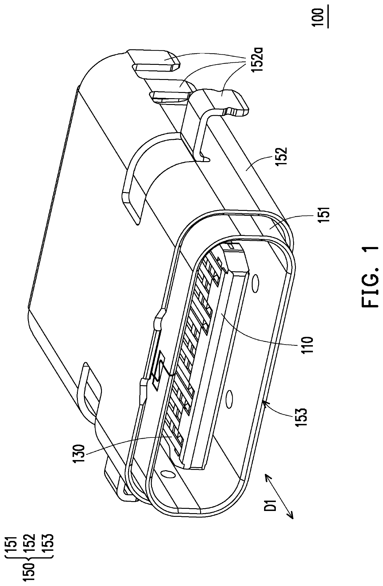
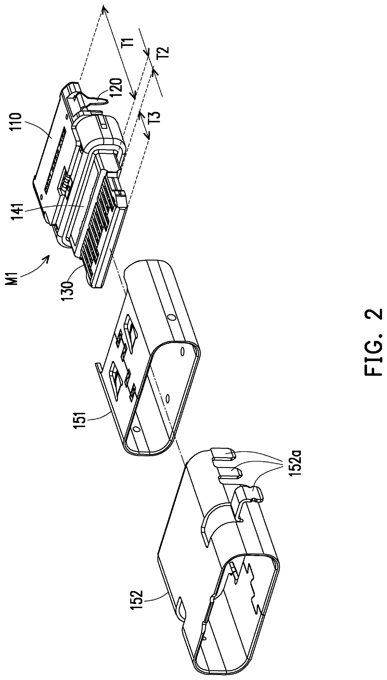
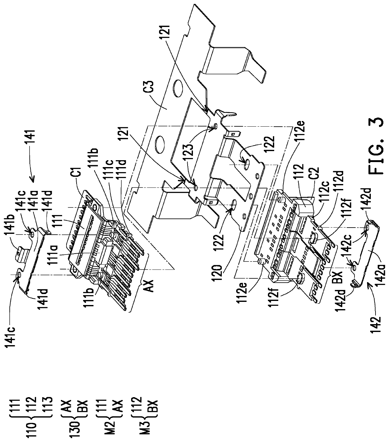
[0016]FIG. 1 is a schematic diagram of an electrical connector according to an embodiment of the disclosure. FIG. 2 is a schematic dissembled diagram of the electrical connector of FIG. 1. FIG. 3 is a schematic diagram illustrating assembling and combining the electrical connector of FIG. 1. Referring to FIG. 1 to FIG. 3 together, in the embodiment, an electrical connector 100 includes an insulating body 110, a first EMI (Electromagnetic Interference) metallic member 141, a second EMI metallic member 142, multiple terminals 130, and a metallic shell 150. The insulating body 110 is divided into a base portion T1, a thickened step portion T2, and a tongue portion T3. The terminals 130 are disposed in the insulating body 110, and portions of the terminals 130 exposed out from the tongue portion T3 are provided for the electrical connector 100 to abut against multiple terminals (not shown) of another electrical connector (not shown) when the electrical connector 100 is connected to the ...


PUM

PropertyMeasurementUnit
metallicaaaaaaaaaa
volumeaaaaaaaaaa
structural strengthaaaaaaaaaa

Abstract

An electrical connector including an insulating body, a first metallic member, a second metallic member, a plurality of terminals, and a metallic shell is provided. The insulating body has a base portion, a thickened step portion, and a tongue portion. The thickened step portion is located at a root of the base portion. The first metallic member and the second metallic member are disposed on an upper surface and a lower surface of the insulating body. The metallic shell is disposed on an exterior of the insulating body to surround the first metallic member, the second metallic member, and the terminals, wherein the front flat contact portion of each of the terminals is exposed out of the tongue portion, and a portion of the first metallic member and a portion of the second metallic member are exposed out of the thickened step portion.

Description

CROSS-REFERENCE TO RELATED APPLICATION[0001]This application claims the priority benefit of China application serial no. 202110236611.6, filed on Mar. 3, 2021. The entirety of the above-mentioned patent application is hereby incorporated by reference herein and made a part of this specification.BACKGROUNDTechnical Field[0002]The disclosure relates to an electrical connector.Description of Related Art[0003]Generally, an electrical connector insertion opening is universal serial bus (USB), which is widely used due to its relatively compact volume and portability and is common in connecting holes of various portable electronic devices, such as smart mobile communication devices and digital cameras, and disposed on and connected to corresponding transmission lines. However, with the miniaturization of electrical connectors, there may be difficulties in manufacturing due to the manufacturing process or the miniaturization of components, leading to a complex manufacturing process and an i...

Claims


Application Information

Patent Timeline
Patent Type & Authority Applications(United States)
IPC IPC(8): H01R13/6586
CPCH01R13/6586H01R13/502H01R13/40H01R13/46H01R2201/06H01R24/60H01R13/6581H01R13/504H01R13/514H01R13/658H01R13/648
Inventor CHEN, CHINGTIENWAN, WEIWU, HUA-YAN
Owner ADVANCED CONNECTEK INC
Why Eureka
Try Eureka