Method for detection of flat wheel deformation by vibration measurement from rails

Pending Publication Date: 2022-09-29
GOKMEN SABRI HALUK
View PDF0 Cites 0 Cited by
  • Summary
  • Abstract
  • Description
  • Claims
  • Application Information

AI Technical Summary

Problems solved by technology

In addition, while performing this process, it uses only the vibrations on the rail and does not evaluate the vibrations occurring

Method used


Image

  • Method for detection of flat wheel deformation by vibration measurement from rails

Examples


Embodiment Construction

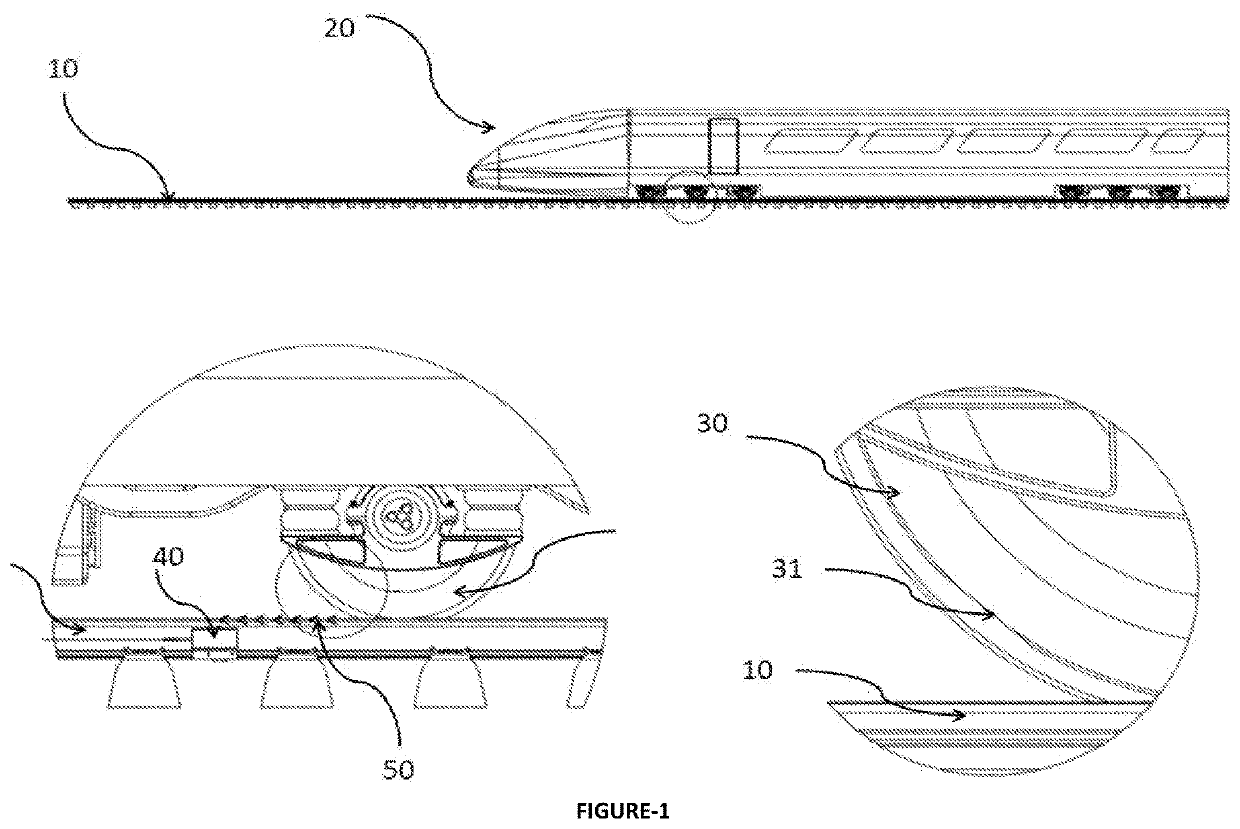
[0030]In the FIG. 1, the drawing showing schematically, the working principle of the method that can be used in determining the flat wheel deformations (31) formed on the wheels (30) of the railway vehicles (20) of the present invention is given.

[0031]The vibration sensor (40) module mounted on the rails (10) are used to measure the vibration waves (50) caused by the wheels (30) with flat wheel deformation (31) of the approaching or moving away railway vehicle (20), in three axis (x, y, z). At the end of the fft (fast fourier transformation) analysis of the data set obtained as a result of the measurement of these vibration waves (50), a flat wheel deformation (31) related signal, which is caused by the wheel (30), by considering the speed of the railway vehicle (20) and the temperature of the rail (10), is revealed to exist. As a result of the perception of the frequency, the presence of the flat wheel deformation (31) is decided. Then, the severity of flat wheel deformation (31) i...


PUM


Abstract

The invention relates to a method that can be used in the field of rail systems technology to detect the flat wheel deformation (31) condition in the wheels (30) of the railway vehicle (20). In particular, the invention is concerned with the detection and analysis of the mechanical vibrations, generated by the vibration waves (50) from the wheels (30) moving on the rails (10) with the vibration sensors (40). Hence, it relates to the method for determining the presence and severity of the flat wheel deformation (31) condition in the wheels (30) of the railway vehicle (20).

Description

TECHNICAL FIELD[0001]The invention relates to a method that can be used in the field of rail systems technology for detecting the flat wheel deformations on the wheels of railway vehicles.[0002]In particular, the invention relates to the method of analyzing the mechanical vibration waves generated by the wheels of the rail vehicles moving on the rails, by means of vibration sensors on the rails, thereby determining the flat wheels of the railway vehicles.PREVIOUS TECHNIQUES[0003]Railway systems in the world are gaining importance day by day because they are fast, economical, environmentally friendly, safe and modern systems. One of the most important features of the rail transportation systems is that they are accepted to be the highest-safety and comfortable public transportation means. Sustaining this feature can be achieved with regular maintenance efforts to these systems. Among these efforts, the maintenance of the wheels of railway vehicles has an important place. As a result ...

Claims


Application Information

Patent Timeline
IPC IPC(8): B61K9/12G01M17/10G01M13/045
CPCB61K9/12G01M17/10G01M13/045B61L15/0081
Inventor GOKMEN, SABRI HALUK
Owner GOKMEN SABRI HALUK
Why Eureka
Try Eureka