
Monohedral tiled antenna arrays

a monohedral tile and antenna array technology, applied in the direction of modular arrays, feeding systems of particular arrays, radiating element structural forms, etc., can solve the problems of undesirable electrical parasitics and antenna assembly complexity

Active Publication Date: 2022-09-29
CAES SYST LLC
View PDF3 Cites 0 Cited by
  • Summary
  • Abstract
  • Description
  • Claims
  • Application Information

AI Technical Summary

Benefits of technology

This patent is about a new kind of antenna that can be customized, made larger or smaller, and work in a variety of frequency ranges. It can be tested and calibrated at a smaller level before being integrated into a larger system, which saves time and money. Overall, this new antenna design is flexible, scalable, and cost-effective.

Problems solved by technology

However, it has been a challenge to integrate multiple mechanical, electrical, and thermal functional components within a limited space of each antenna unit.
Some of the functional components of each antenna unit have to be moved out of the antenna unit and disposed remotely on an antenna level, which introduces undesirable electrical parasitics and assembly complexity to the antenna.

Method used


Image

  • Monohedral tiled antenna arrays
  • Monohedral tiled antenna arrays
  • Monohedral tiled antenna arrays

Examples


Embodiment Construction

[0061]Numerous details are described herein in order to provide a thorough understanding of the example embodiments illustrated in the accompanying drawings. However, some embodiments may be practiced without many of the specific details, and the scope of the claims is only limited by those features and aspects specifically recited in the claims. Furthermore, well-known processes, components, and materials have not been described in exhaustive detail so as to avoid obscuring pertinent aspects of the embodiments described herein.

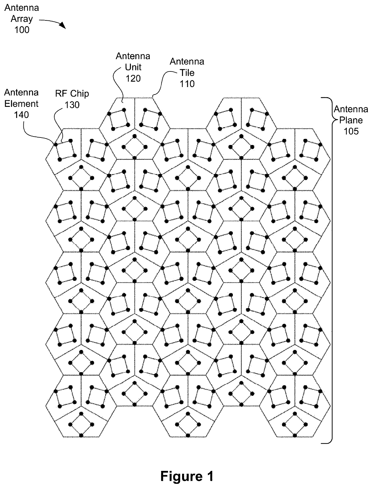
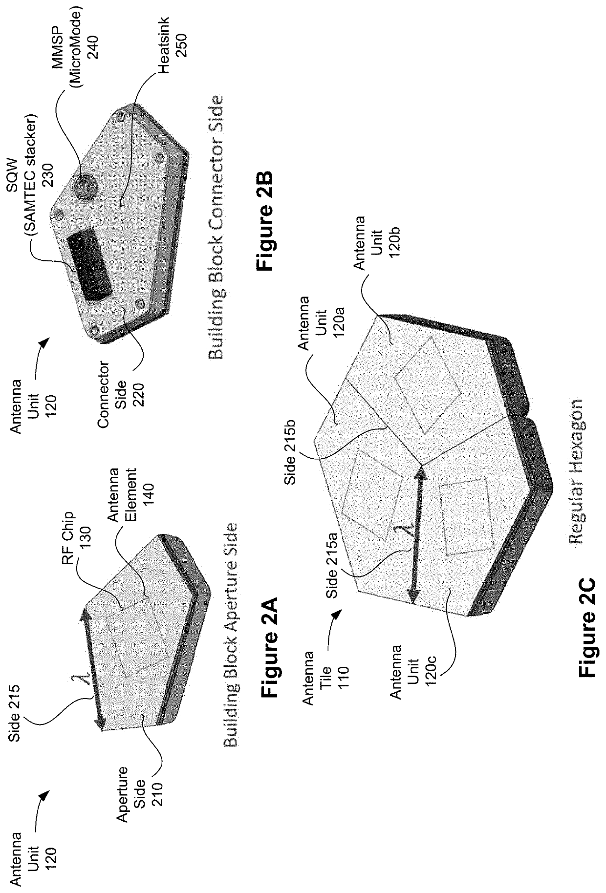
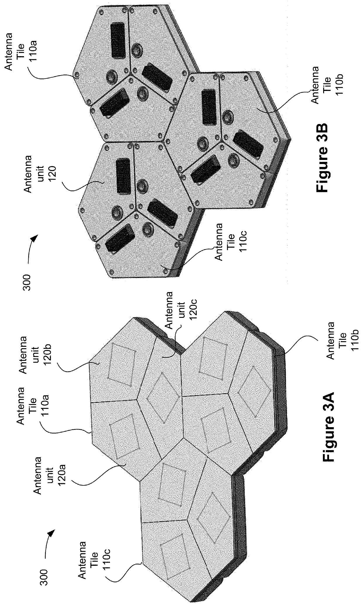
[0062]In some implementations of this application, an antenna (also called antenna array when it includes more than one antenna unit) includes an antenna unit having a pentagonal shape and configured to be arranged with one or more additional antenna units to form an antenna tile having a hexagonal shape. In some embodiments, the antenna further includes at least one additional antenna tile that is substantially identical to the antenna tile, i.e., monohedral...


PUM


Abstract

An antenna array includes one or more antenna tiles which are arranged on an antenna plane. Each of the one or more antenna tiles includes one or more antenna units that are arranged together to form the respective antenna tile having a hexagonal shape and each antenna unit comprises an antenna circuit chip. In some embodiments, each antenna unit has a pentagonal shape and the antenna tile has a hexagonal shape formed by tessellating the one or more antenna units with one another.

Description

CROSS REFERENCE TO RELATED APPLICATIONS[0001]This application claims the benefit of U.S. Provisional Patent Application No. 63 / 166,222, filed Mar. 25, 2021. The entire contents of the application are incorporated herein by reference.TECHNICAL FIELD[0002]The disclosed embodiments relate generally to antenna technology, including but not limited to methods and systems associated with a directional antenna array with monohedral tiling of antenna units, where each unit accommodates additional functional components (e.g., interconnects, connectors, active and passive electronic devices, and heat sinks).BACKGROUND[0003]Multiple antenna units are often connected to work as a single antenna or an antenna array for receiving or transmitting radio waves. In such an antenna or antenna array, individual antenna units are controlled with correlated phases to create a steerable beam of radio waves pointing in different directions without moving the antenna array. Each antenna unit has a dimension...

Claims


Application Information

Patent Timeline
Patent Type & Authority Applications(United States)
IPC IPC(8): H01Q21/00H01Q1/22H01Q1/38H01Q1/02
CPCH01Q21/0025H01Q1/2283H01Q1/38H01Q1/02H01Q21/061H01Q3/38
Inventor SIMON, MICHAEL JASONPORS, MICHAEL SCOTTKATHOL, BRYAN
Owner CAES SYST LLC
Learn More