Fixture connection assembly

a technology for connecting assemblies and light fixtures, applied in fixed installations, lighting and heating devices, lighting support devices, etc., can solve problems such as water exposure to electrical wiring, reduce the operating life of light fixtures, and may not protect light fixture electrical wiring from water leakage, so as to reduce water leakage

Pending Publication Date: 2022-10-06
BARN LIGHT ELECTRIC CO LLC
View PDF13 Cites 1 Cited by
  • Summary
  • Abstract
  • Description
  • Claims
  • Application Information

AI Technical Summary

Benefits of technology

[0011]In some embodiments, the bores may create a hollow passage capable of housing electrical wiring when the internal threads of a stem engage the external threads of the top connector, which may include internal threads that engage the external threads of the bottom connector. Coupling of the top connector with the light fixture shade may create a seal to reduce water leakage.

Problems solved by technology

However, in outdoor applications, as well as indoor applications with high humidity, the fasteners may not protect the electrical wiring of the light fixture from water-leakage.
Exposure of electrical wiring to water creates an electrical hazard.
Progressive water damage to the circuitry may reduce the operating lifetime of the light fixture.
Water exposure may also affect the surfaces of the light fixture.
For example, rust may form on the surfaces of the light shade that adjoin to the components of the connection assembly.
Damage may be exasperated in hanging light fixtures that do not provide a secure covering for the electrical wiring, as gravity in combination with other external forces may cause the connection assembly to loosen and open over time.

Method used


Image

  • Fixture connection assembly
  • Fixture connection assembly
  • Fixture connection assembly

Examples


Embodiment Construction

[0043]Reference will now be made in detail to the embodiments of the present disclosure, examples of which are illustrated in the accompanying drawings.

Connection Assembly

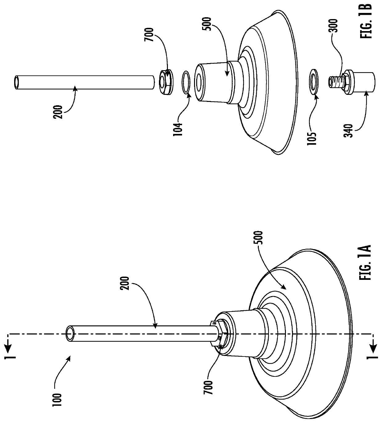
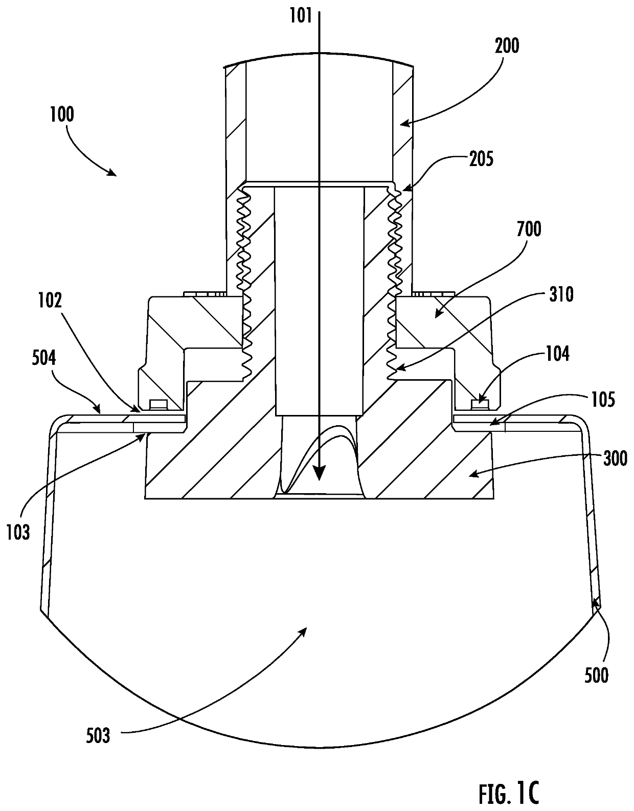
[0044]With reference to FIGS. 1-7, the present disclosure may be embodied as a connection assembly 100 that includes a stem 200 and two connectors 300, 700. FIG. 1A illustrates a connection assembly 100 in an assembled state, which may comprise a downward facing light fixture 400 suspended from a ceiling (not shown) via the stem 200. In some embodiments, the two connectors 300, 700 constitute a bottom connector 300 and a top connector 700. As illustrated in FIGS. 1B-1C and 4B, at least one connector 300 may be configured to engage the stem 200. The two connectors 300, 700 may be configured to couple, directly or indirectly, to a light fixture shade 500.

Stem

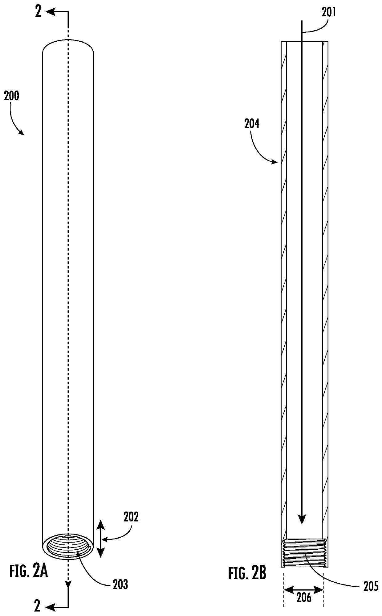
[0045]Referring to FIGS. 2A-2B, the stem 200 may contain a longitudinal stem-bore 201 and an end-portion 202. The end-portion 202 may define a stem-opening 203 t...


PUM


Abstract

A light fixture connection assembly includes an internally threaded stem and two connectors that couple with a top surface and a bottom surface of a light fixture shade. Bores throughout the stem and connectors define a passageway for electrical wiring connected to a light sourced within the light fixture shade. The connection assembly reduces water-leakage into the hollow passage, and prevents electrical hazards and premature termination of the useable life of the light fixture.

Description

[0001]This non-provisional patent application claims priority to, and incorporates herein by reference, U.S. Provisional Patent Application No. 62 / 874,644 that was filed Jul. 16, 2019.FIELD OF THE DISCLOSURE[0002]This disclosure relates generally to light fixtures, and more particularly to light fixture connection assemblies including a set of couplers for mounting a light shade on a post or stem.BACKGROUND[0003]Outdoor light fixture shades are commonly used to protect light bulbs from environmental elements, including rainwater. A light shade is typically attached to a light fixture connection assembly using conventional metal fasteners that screw onto the exterior surface of a threaded post, which houses the electrical wiring for the light fixture. The fasteners commonly employ two threaded nuts: one engaging an exterior surface of the light fixture shade, and the other engaging an interior surface of the light fixture shade.[0004]The fasteners hold the light fixture shade onto th...

Claims


Application Information

Patent Timeline
Patent Type & Authority Applications(United States)
IPC IPC(8): F21V21/112F21V17/12
CPCF21V21/112F21V17/12F21S8/063F21V31/005
Inventor LEATHLEAN, MARK LEE
Owner BARN LIGHT ELECTRIC CO LLC
Why Eureka
Try Eureka