Rotary Control Input Device for a Capacitive Touch Screen

a capacitive touch and input device technology, applied in the direction of mechanical control devices, instruments, computing, etc., can solve the problems of inability to provide the degree of precision of traditional controls such as potentiometers, linear faders, shaft encoders, etc., and the lack of tactile feedback provided by touch screens does not allow the development of motor memory

Pending Publication Date: 2022-10-06
QUIXANT
View PDF2 Cites 0 Cited by
  • Summary
  • Abstract
  • Description
  • Claims
  • Application Information

AI Technical Summary

Benefits of technology

[0017]The sealing element may be configured to inhibit ingress of moisture and foreign bodies into the rotary control input device.
[0021]Embodiments of the present invention seek to provide high precision rotary knobs for use within the active display / touch area of an LCD display so graphics and text can be located immediately adjacent to the button, and also the area behind the knob. Precision in this context covers parameters such as: low starting torque for rotation, low or zero constant torque during rotation, very low backlash, and good angular resolution of incremental rotation.
[0022]To provide this precision and to solve the problem of tactile feedback through operational control objects, the inventors have invented a rotary knob that conducts human capacitance through a user contact area to an electrode which is not in contact with the capacitive touchscreen. This feature means that the electrodes do not wear against the glass of the touch screen.
[0023]These electrodes induce a capacitance in the touch sensor which enables the position of the electrode to be detected and through software and firmware. This allows the user to provide input to the system by virtue of the angular position of the rotary knob.

Problems solved by technology

For complex operations such as audio mixing, however, there are a number of problems with the use of touch screen controls.
Firstly, manual operation of a touch screen is unable to provide the degree of precision of traditional controls such as potentiometers, shaft encoders, linear faders, and electro-mechanical switches.
Secondly, the lack of tactile feedback provided by a touch screen does not allow the development of motor memory, essential to enable a user to concentrate on complex tasks while interacting with the control interface.
However, switches alone can only provide so much functionality.

Method used


Image

  • Rotary Control Input Device for a Capacitive Touch Screen
  • Rotary Control Input Device for a Capacitive Touch Screen
  • Rotary Control Input Device for a Capacitive Touch Screen

Examples


Embodiment Construction

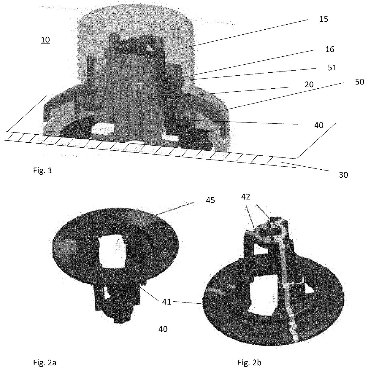
[0032]FIG. 1 is a cross-sectional view of a rotary control input device according to one embodiment.

[0033]The rotary control input device 10 includes a mounting element 20 for retaining the device in place on a capacitive touch screen 30 and a circuit frame 40 rotatably mounted on the mounting element 20.

[0034]The circuit frame 40 includes a rotation electrode 45, the rotation electrode being disposed to be adjacent and spaced apart from the capacitive touch screen 30 when the device 10 is retained in place.

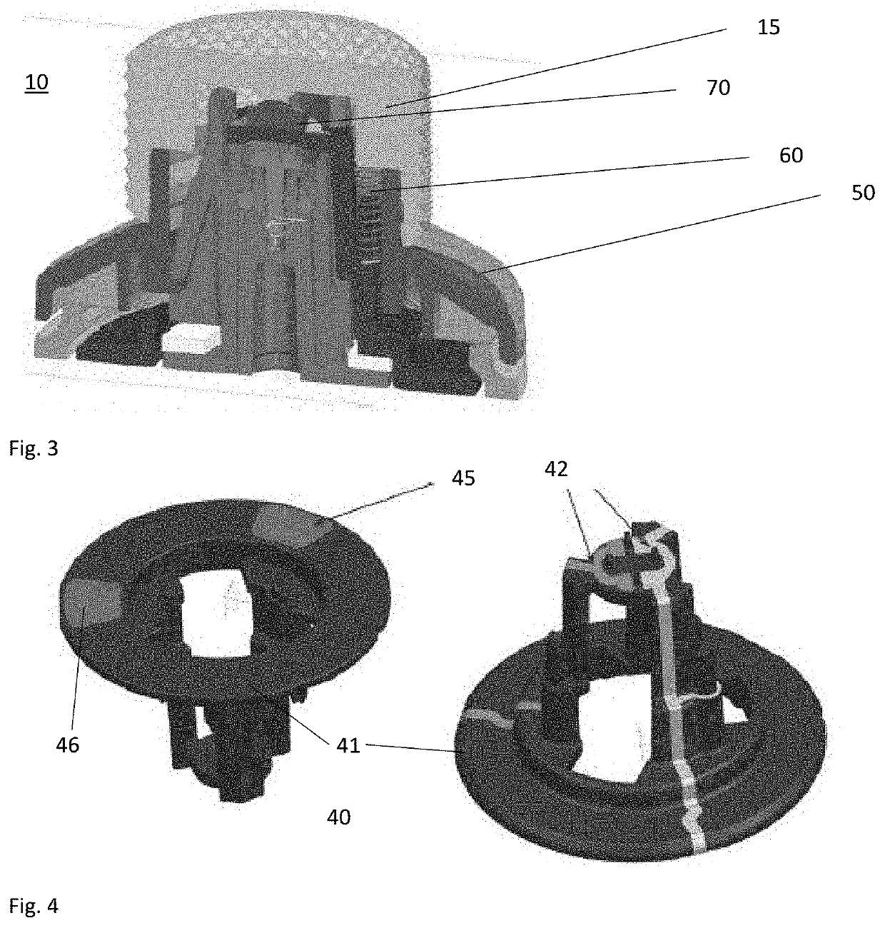
[0035]The device 10 includes a conductive body portion 15 that is electrically connected to the rotation electrode 45. The circuit frame 40 is rotatable about the mounting element 20, with respect to the capacitive touch screen 30, by a user via the conductive body portion 15.

[0036]In this embodiment, the conductive body portion 15 is in the form of a separate knob that is connected to the circuit frame 40. However, it will be appreciated that it may be an integrally moulded piec...


PUM


Abstract

A rotary control input device for a capacitive touch screen is disclosed. The control device comprises a mounting element for retaining the device in place on the capacitive touch screen, a circuit frame rotatably mounted on the mounting element, the circuit frame including a rotation electrode, the rotation electrode being disposed to be adjacent and spaced apart from the capacitive touch screen when the device is retained in place. The device further includes a conductive body portion that is electrically connected to the rotation electrode, the circuit frame being rotatable about the mounting element, with respect to the capacitive touch screen, by a user via the conductive body portion.

Description

CROSS-REFERENCE TO RELATED APPLICATION[0001]This application claims priority under 35 U.S.C. § 119 to GB Patent Application No. 2104541.4 filed Mar. 30, 2021, the contents of which are hereby incorporated by reference in its entirety as if set forth herein.FIELD OF THE INVENTION[0002]The present invention related to a rotary control input device for a capacitive touch screen that is particularly applicable for use in complex interfaces and those in which a user might be navigating only or primarily by touch.BACKGROUND[0003]Capacitive touch screens are an increasingly common input method for software and computer based systems across many industries and applications. They offer versatility, simplicity of operation, and compactness.[0004]For complex operations such as audio mixing, however, there are a number of problems with the use of touch screen controls.[0005]Firstly, manual operation of a touch screen is unable to provide the degree of precision of traditional controls such as p...

Claims


Application Information

Patent Timeline
Patent Type & Authority Applications(United States)
IPC IPC(8): G06F3/039G06F3/0362G06F3/044
CPCG06F3/0393G06F3/0362G06F3/044G05G1/10G06F3/039G05G1/08H01H25/06
Inventor EBERWEIN, FABIANKRALL, HANSPETER
Owner QUIXANT
Why Eureka
Try Eureka