Hydraulic pressure relief depressurization valve assembly for quick coupling

Pending Publication Date: 2022-10-13
DYNAMICS DO BRASIL METALURGIA
View PDF0 Cites 0 Cited by
  • Summary
  • Abstract
  • Description
  • Claims
  • Application Information

AI Technical Summary

Benefits of technology

[0026]The present invention features a hydraulic pressure relief depressurization valve assembly for quick coupling providing greater variability in the application and use of t

Problems solved by technology

However, when it is necessary to stop the hydraulic system, whether for maintenance or tool replacement, the system will remain pressurized and the disconnection or connection of the quick coupling will be complicated and heavy, and it is sometimes necessary to use tools for this disconnection, which can damage the couplings or being necessary to manipulate the lines in order to relieve the pressure and facilitate the connection.
However, this device has a complex embodiment that makes it difficult to manufacture and adapt to any hydraulic system, another aggravating factor being that the depressurization valve is in the same body as the quick coupling, which does not allow the use of more than one quick coupling model.
However, this embodiment has several elements in order to present a complex embodiment that makes its manufacture difficult and that generates several inconveniences, mainly due to the need to carry out maintenance of the sealing elements, which has a g

Method used


Image

  • Hydraulic pressure relief depressurization valve assembly for quick coupling
  • Hydraulic pressure relief depressurization valve assembly for quick coupling
  • Hydraulic pressure relief depressurization valve assembly for quick coupling

Examples


Embodiment Construction

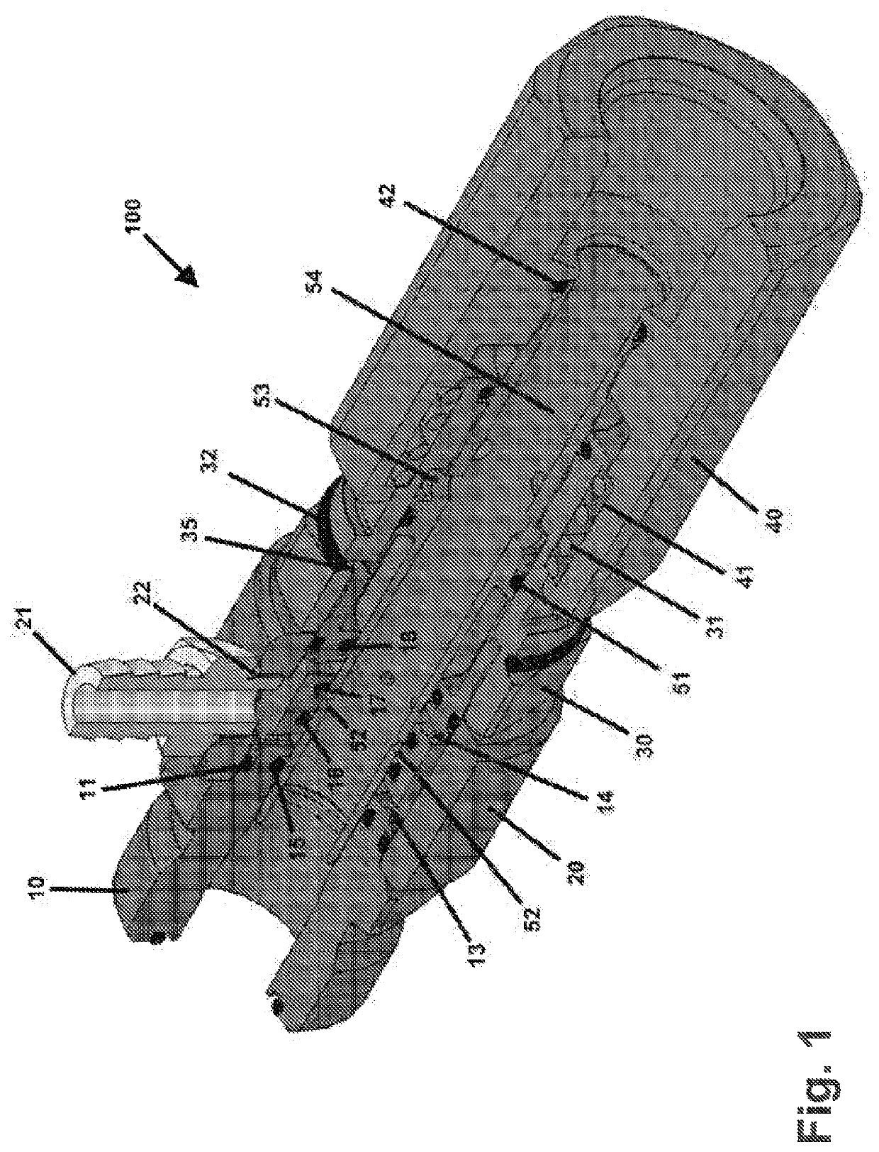
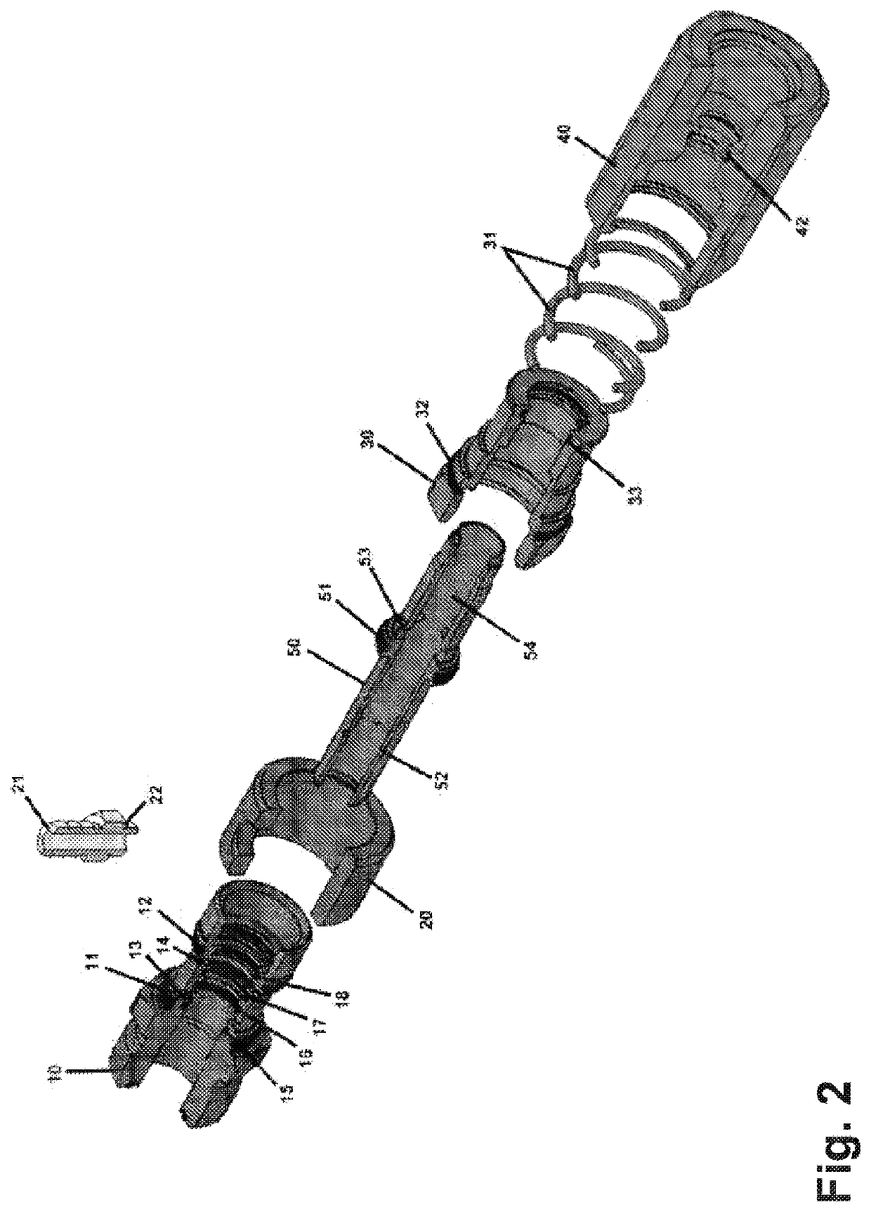
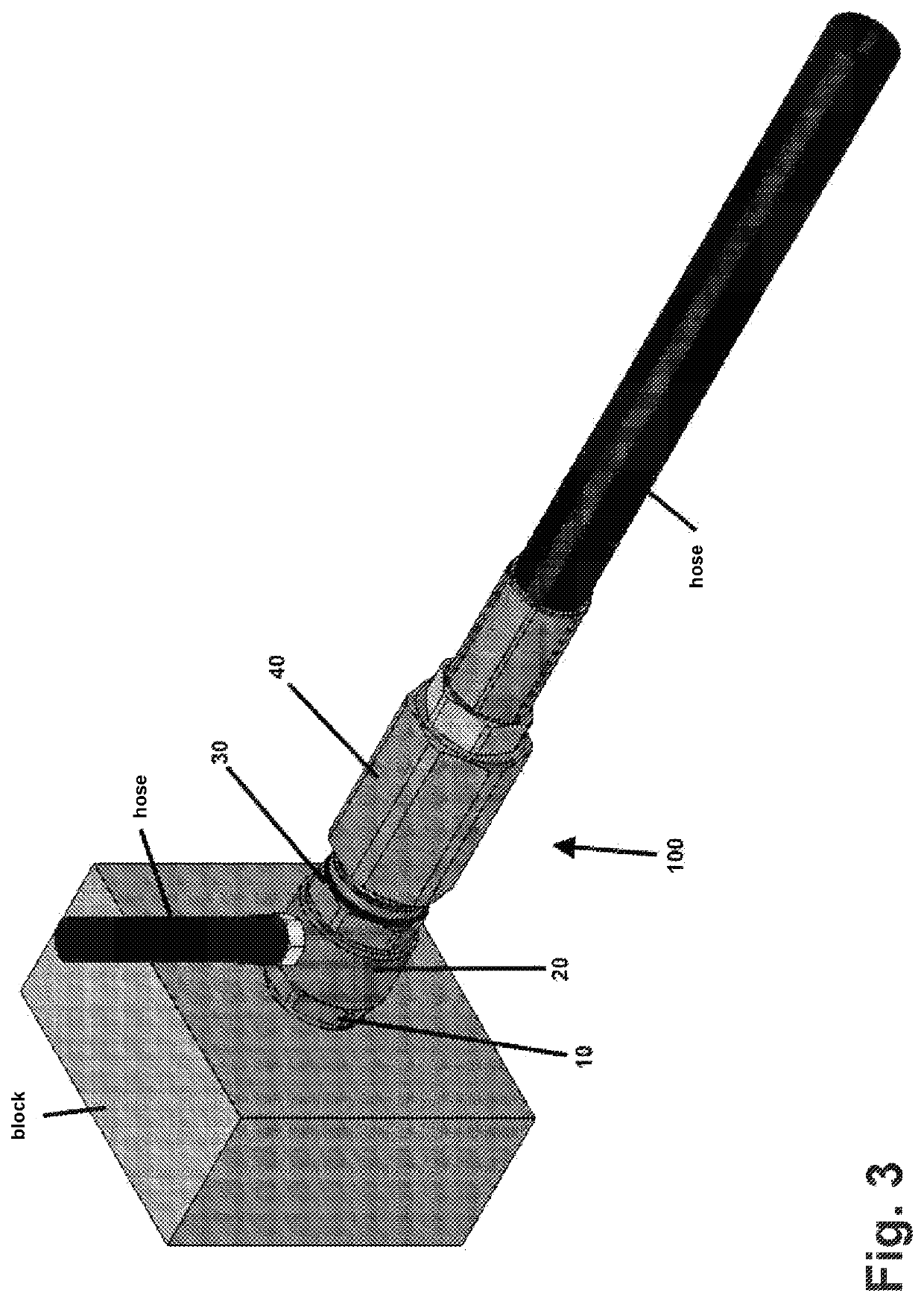
[0049]The hydraulic pressure relief depressurization valve assemble for quick coupling, object of the present invention, comprises a directional fluid body (10), a tank access manifold (20), an intermediate sleeve (30), a hydraulic system coupling gantry (40) and an axial displacement equalized relief valve (50), forming the valve assemble (100) that allows relieving the pressure in the connection and disconnection action, in order to minimize the pressure forces and facilitate the installation and replacement of the hoses to the line of hydraulic systems.

[0050]The directional fluid body (10) has grooves in its outer portion that enable the arrangement of sealing elements (11) and (12) together with the attachment means of the tank access manifold (20). On the inner portion of the body (10) are arranged grooves (13) and (14) interspersed by a pressurized seal (15), rear directional coupling seal (16), lower directional coupling seal (17) and depressurization safety seal (18), allowi...


PUM


Abstract

The hydraulic pressure relief depressurization valve assembly for quick coupling which is object of the present invention comprises a depressurization valve assembly (100) and (200) that can be assembled in any quick coupling that has a directional body (10) and (60), generally fixed to a manifold with access to the tank (20), an intermediate sleeve (30) and (80) and a port (40) for connection to the hydraulic system, inside which is a relief valve (50) and (90), that moves axially, provided with directional holes that make it possible to relieve the pressure during the connection and disconnection action (during the manual push and pull movement), so as to minimize the pressure forces and facilitate the installation and replacement or changing of hoses on the hydraulic line.

Description

FIELD OF THE INVENTION[0001]The present invention describes a hydraulic pressure relief depressurization valve assemble that can be fitted together with any quick coupling model. More specifically, it comprises a valve assemble equipped with an innovative relief valve system, which allows the residual depressurization of the hydraulic system, allowing a quick coupling to be coupled and uncoupled to the hydraulic system without major difficulties. One of the main problems for quick coupling connection and disconnection is due to residual pressure in the line.BACKGROUND OF THE INVENTION[0002]Hydraulic systems are used for the generation, control and transmission of energy through pressurized fluids, and in these systems the power is transmitted and controlled through a fluid under pressure in a closed loop.[0003]Hydraulic systems used in industrial equipment and machinery are normally equipped with a quick coupling system that allows connecting and disconnecting the fluid conduction l...

Claims


Application Information

Patent Timeline
IPC IPC(8): F16L37/36F16L37/34
CPCF16L37/36F16L37/34F16K3/262F16K3/265
Inventor MANZATO, FERNANDO
Owner DYNAMICS DO BRASIL METALURGIA
Why Eureka
Try Eureka