
Plastic glide layer and sliding element with such

a glide layer and sliding element technology, applied in the field of sliding bearings, can solve the problems of delamination of the sliding layer, inability to re-machine the sliding layer mechanically without difficulty, and inability to meet the requirements of all applications, etc., and achieves the effects of high wear resistance, easy production, and easy re-machined

Active Publication Date: 2013-01-22
FEDERAL MOGUL DEVA
View PDF14 Cites 0 Cited by
  • Summary
  • Abstract
  • Description
  • Claims
  • Application Information

AI Technical Summary

Benefits of technology

[0009]The object of this invention is therefore to provide a sliding layer or sliding element which such a sliding layer based on a fiber reinforced plastic, which is easy to produce, can easily be re-machined and has a high wear resistance with good sliding properties.
[0011]This has the advantage over the twisted fibers of prior art of greater variability in the content of the individual components of the thread / fiber, particularly its PTFE content. Therefore its properties can be modified much more precisely even during the production of the plastic thread. Due to the fact that the PTFE particles do not adhere together, unlike the PTFE filament, i.e. due to the PTFE particles arranged and anchored randomly inside the polyester filaments, the plastic thread has a roughed up appearance and a better adhesive bond is achieved between the plastic thread and the plastic matrix. Finally, the binding of the PTFE particles in the plastic thread reinforces the mechanical retention of the same, due mainly to positive mechanical engagement.
[0012]The sliding layer may therefore be satisfactorily machined mechanically, i.e. with cutting. The use of the plastic thread with PTFE particles in the sliding layer is therefore particularly suitable for precision sliding bearings which have, for example, to be re-machined by drilling, honing or the like to a final dimension. The sliding layer according to the invention or the sliding element according to the invention also opens up other areas of application because lubrication or dirt grooves, for example, can be worked into the sliding layer, with the aid of which particles or lubricants can be specifically removed or supplied. In addition to the improved machinability, improved wear values, particularly in terms of depth wear, are also achieved because of the improved binding of the PTFE particles.
[0013]The sliding layer according to the invention also has advantages over the prior art sliding layers with PTFE particles as a solid lubricant in the plastic matrix. For as a solid lubricant in the plastic matrix PTFE also has a strength reducing action, thus impairing the tribological properties at high load and in an aqueous environment, and while the PTFE particles in the plastic matrix are in most cases distributed inhomogeneously because of the different material thickness, the distribution of the particles throughout the sliding surface is highly homogeneous since the particles are solidly bound in the fiber / thread which extends throughout the thickness of the sliding layer. Due to the improved homogeneity and improved mechanical binding, improved tribological properties are also ultimately achieved. This applies to both dry running and its use in an aqueous environment.
[0025]Just as for the plastic matrix of the sliding layer, epoxy resin is also suitable as a plastic matrix for the support layer due to excellent adhesion properties, mechanical and dynamic properties. Because of its molecular structure epoxy resin also has very good moisture resistance and comparatively little tendency to swell. Because the same plastic matrix is used in the sliding and support layer, the binding forces between the sliding layer and the support layer are also increased.
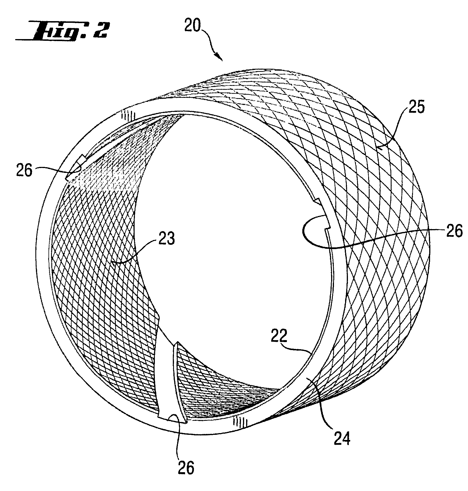
[0027]If the sliding layer and support layer are deposited in succession on a winding mandrel in the winding process, this increases the efficiency of the production of the compound bearing material.

Problems solved by technology

Although the use of PTFE as a solid lubricant has proved satisfactory in fiber reinforced plastic sliding layers due to its good sliding friction properties, tribological and mechanical properties not yet satisfactory for all applications have been achieved.
Consequently the sliding layers of prior art could not be re-machined mechanically without difficulty, or not at all.
In most cases the result was delamination of the sliding layer and deterioration in the tribological properties and in the wear resistance of the siding layer.

Method used


Image

  • Plastic glide layer and sliding element with such
  • Plastic glide layer and sliding element with such
  • Plastic glide layer and sliding element with such

Examples


Embodiment Construction

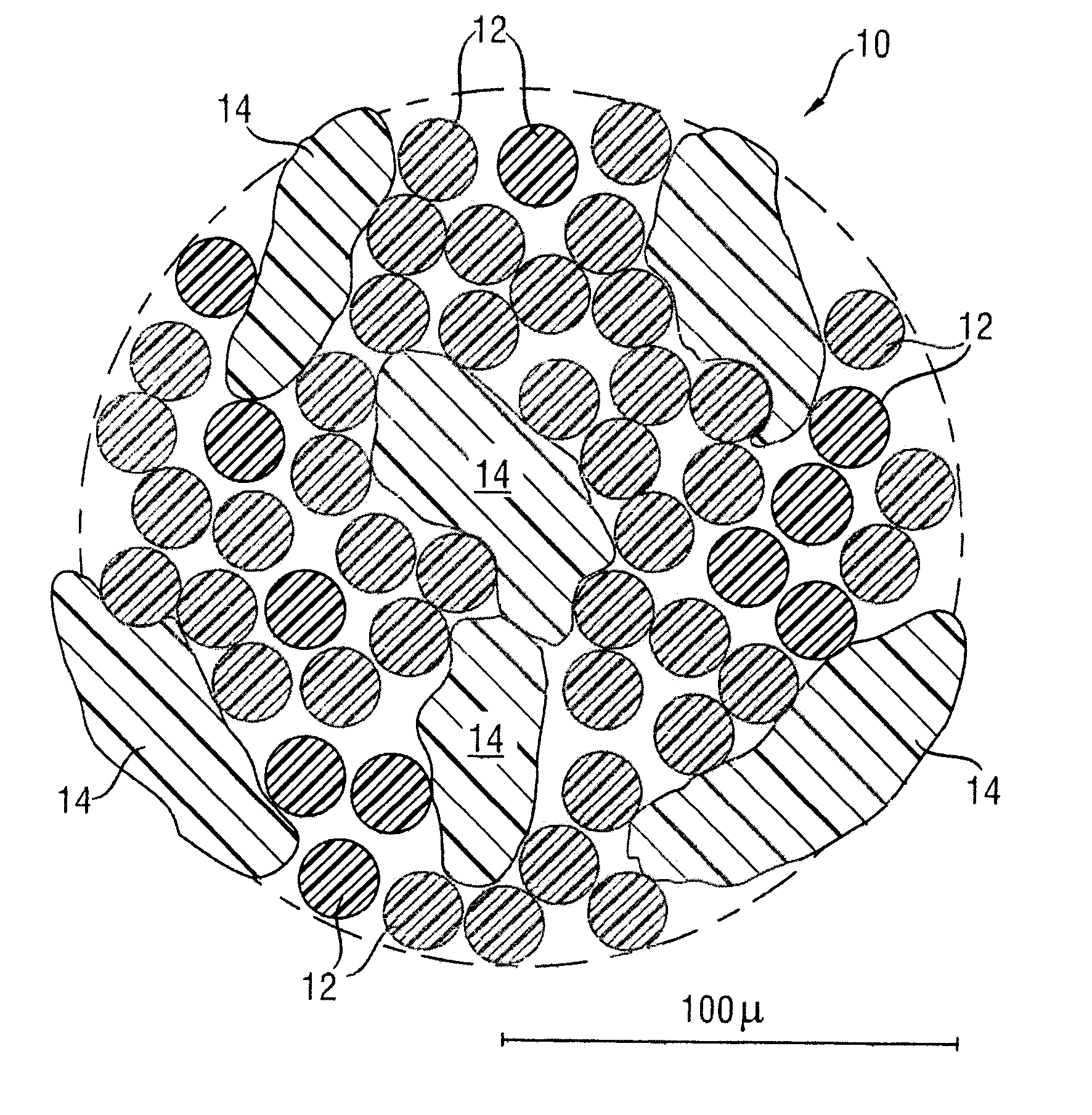
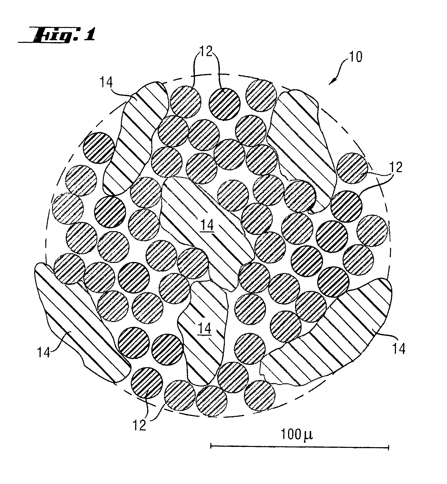
[0033]Plastic thread 10 used according to the invention for the sliding layer of the outer race as a reinforcing element is shown in FIG. 1 in an enlarged sectional representation. This consists of polyester filaments 12 orientated along the thread and contains as a second component PTFE particles 14 which are spun into polyester filaments 12 in a random arrangement. During the production process there are very many possibilities of modifying the properties of the thread. For example, the number of polyester filaments 12 per thread 10 can be varied according to the application, but here attention should be paid to ensuring an adequate positive engagement with the bound in PTFE particles 14.

[0034]The weight ratio of polyester filaments 12 to PTFE particles 14 may also be varied. However, it has proved particularly preferable, in terms of adhesion, friction and sliding characteristic, if the proportion of the PTFE particles 14 in the plastic thread is between 30 and 36% by weight and ...


PUM

PropertyMeasurementUnit
weight ratioaaaaaaaaaa
weightaaaaaaaaaa

Abstract

A sliding layer and a sliding element with such a sliding layer includes a fiber reinforced plastic with a plastic matrix and a plastic thread as a reinforcing element. The plastic thread has polyester filaments into which are worked PTFE particles by process engineering.

Description

RELATED APPLICATIONS[0001]This application claims priority to German Patent Application 10 2006 043 065.4-43, filed Sep. 14, 2006.BACKGROUND OF THE INVENTION[0002]1. Technical Field[0003]The invention relates to a sliding bearing based on fiber-reinforced plastic with a plastic matrix and a plastic thread as reinforcing element. It also relates to a sliding element with such a sliding layer.[0004]2. Related Art[0005]The use of composite fiber materials for sliding bearings, in particular wound plastic sliding bearings based on epoxy resins, is of prior art. Such sliding bearings consist of a single-layer sliding layer material or a bearing material constructed from two layers, a support layer and a sliding layer. The sliding layer may be located on the inside relative to the support layer, according to the application. The support layer is typically characterised by a glass fiber or carbon fiber reinforced epoxy resin matrix which has a very high load absorption capacity. The slidin...

Claims


Application Information

Patent Timeline
Patent Type & Authority Patents(United States)
IPC IPC(8): B32B27/04D02G3/02B32B27/20B32B27/14B32B27/12B29D33/00
CPCB29C70/025F16C33/201B32B27/04C08J5/046B29K2027/18B29K2067/00B29K2267/00B29L2031/04B29K2427/18Y10T442/273Y10T442/2123Y10T442/2311Y10T442/425Y10T428/24994Y10T442/2131F16C2208/86
Inventor ROOS, UDOLAAL RIAHI, KAMRANLINKER, ARMIN
Owner FEDERAL MOGUL DEVA
Learn More