Method for production of a component by atomic diffusion bonding

Active Publication Date: 2021-08-26
ASML NETHERLANDS BV
View PDF0 Cites 0 Cited by
  • Summary
  • Abstract
  • Description
  • Claims
  • Application Information

AI Technical Summary

Benefits of technology

[0053]An essential advantage of the invention lies in the great variability in the selection of plate materials. Material restrictions, such as in the bonding processes used in the prior art, are overcome. The plates are preferably made of glass, in particular low-ion glass e.g. borosilicate glass, in particular glass with trade name Eagle XG (manufacturer Corning), glass ceramic, a crystalline material, in particular sapphire or diamond, ceramic, in particular silicon nitride, aluminium nitrite or aluminium oxide, and/or plastic.
[0054]The bond layers for atomic diffusion bonding may each comprise one single layer or a layer stack of two or more metallic materials. The bond layers comprise e.g. gold (see [14]), platinum, titanium, silver and/or tungsten (see [15], [16]). If the bond layers consist of metals which may react with the surrounding atmosphere, in particular e.g. titanium, silver and/or tungsten, the atomic diffusion bonding is preferably carried out under vacuum or under inert gas in order to avoid reactions of the metals with the environment.
[0055]According to a further advantageous embodiment of the invention, it may be provided that the two plates joined by atomic diffusion bonding are made of different materials. Advantageously, this allows the plates to have different properties, e.g. different electrical parameters, depending on the use of the component. For use as an electrostatic holding device, it is particularly preferred for one of the plates to be made of a material distinguished by a high-voltage disruptive strength of at least 1000 V/mm. The plate with the increased high-voltage disruptive strength may advantageously be provided as a dielectric on the (e.g. top) side of the holding device on which e.g. semiconductor wafers will be held. Alternatively, the mutually joined plates may comprise the same materials.
[005

Problems solved by technology

This method is disadvantageous because of its complexity, in particular when carriers made of electrochemically bonded glass plates are used.
The cover layer however has disadvantages for production of the component, since deposition of the cover layer constitutes an additional process cost and can only be carried out after processing of the metal layer, e.g. structuring by ablation or etching, for its adaptation to the respective application.
Furthermore, the metal layer may be unintentionally changed during deposition of the cover layer.
The technique described in [3] however has the

Method used


Image

  • Method for production of a component by atomic diffusion bonding
  • Method for production of a component by atomic diffusion bonding
  • Method for production of a component by atomic diffusion bonding

Examples


Embodiment Construction

[0069]Preferred features of embodiments of the method according to the invention and the component produced with the method are described below substantially with reference to the preparation of plates, the production of the component by atomic diffusion bonding, and the processing of the metal layer in the atomic diffusion bond. Details of the processing of the metal layer may be implemented as described in [3]. Accordingly, with respect to the features of the processing of the metal layer, [3] is introduced into the present disclosure by reference. Details of the complete structure and application of the component produced according to the invention, for example as an electrostatic holding device, are not described insofar as these are known from the prior art.

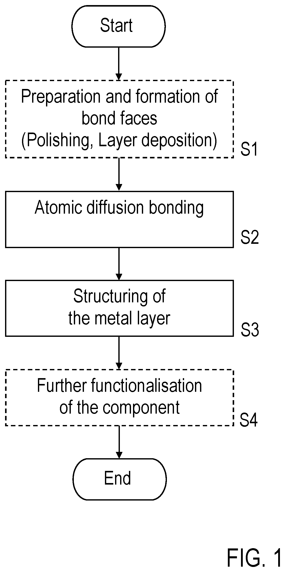
[0070]According to FIG. 1, before production of the component by atomic diffusion bonding, firstly a preparation step S1 takes place in which the plates are provided with the prepared bonding faces. In detail, the preparatio...


PUM

PropertyMeasurementUnit
Electric field strengthaaaaaaaaaa
Surface roughnessaaaaaaaaaa
Temperatureaaaaaaaaaa

Abstract

A method for producing a component from two plates, which are electrically isolating, at least one is optically transparent, and between them at least one planar conductor section and at least one isolator section are formed, comprises bonding the plates at mutually facing bonding faces, wherein a metal layer is arranged therebetween, and processing the metal layer by local heating using laser radiation such that the metal layer is converted into the at least one isolator section in a part region, and the at least one conductor section is formed adjacent thereto. To form the at least one isolator section, the light path of the laser radiation and the component are moved relative to each other to convert the metal layer into the at least one isolator section over a line or area. Bonding faces of metallic bond layers are polished. The plates are bonded by atomic diffusion bonding.

Description

BACKGROUND OF THE INVENTION[0001]The invention concerns a method for production of a component from two plates, wherein both plates are electrically isolating, at least one of the plates is optically transparent, and at least one planar conductor section and at least one isolator section are formed between the plates; in particular, it concerns a method for processing a component with a sandwich structure in which a metal layer is embedded, e.g. a method for processing a component composed by bonding, wherein the component has a metallic intermediate layer.[0002]Applications of the invention lie in the production of tools for holding or moving workpieces, such as e.g. semiconductor wafers or glass wafers, under the effect of electrical fields, or in the production of conductor components, in particular resistance heating elements.[0003]In the present description, reference is made to the following prior art which constitutes the technical background to the invention:[0004][1] US 709...

Claims


Application Information

Patent Timeline
IPC IPC(8): B23K20/02B23K20/00B23K20/24
CPCB23K20/026B23K2103/54B23K20/24B23K20/002B23K20/02B23K2103/52B23K26/352B23K2103/42
Inventor INGWERSEN, JANKIEVEN, DAVID
Owner ASML NETHERLANDS BV
Why Eureka
Try Eureka