
Coil Support

Pending Publication Date: 2022-10-13
SIEMENS HEALTHCARE LTD
View PDF0 Cites 1 Cited by
  • Summary
  • Abstract
  • Description
  • Claims
  • Application Information

AI Technical Summary

Benefits of technology

The patent discusses a way to support superconducting magnets to prevent them from buckling and distorting the magnetic field they generate. The solution is to provide continuous support around the entire circumference of the magnet, which reduces stress concentrations and avoids buckling modes. This approach results in a more uniform magnetic field and reduces the need for expensive and heavy structures.

Problems solved by technology

It may be problematic to support these shield coils in an efficient and cost-effective manner.

Method used


Image

  • Coil Support
  • Coil Support
  • Coil Support

Examples


Embodiment Construction

[0014]In the following description, numerous specific details are set forth in order to provide a thorough understanding of the embodiments of the present disclosure. However, it will be apparent to those skilled in the art that the embodiments, including structures, systems, and methods, may be practiced without these specific details. The description and representation herein are the common means used by those experienced or skilled in the art to most effectively convey the substance of their work to others skilled in the art. In other instances, well-known methods, procedures, and components have not been described in detail to avoid unnecessarily obscuring embodiments of the disclosure.

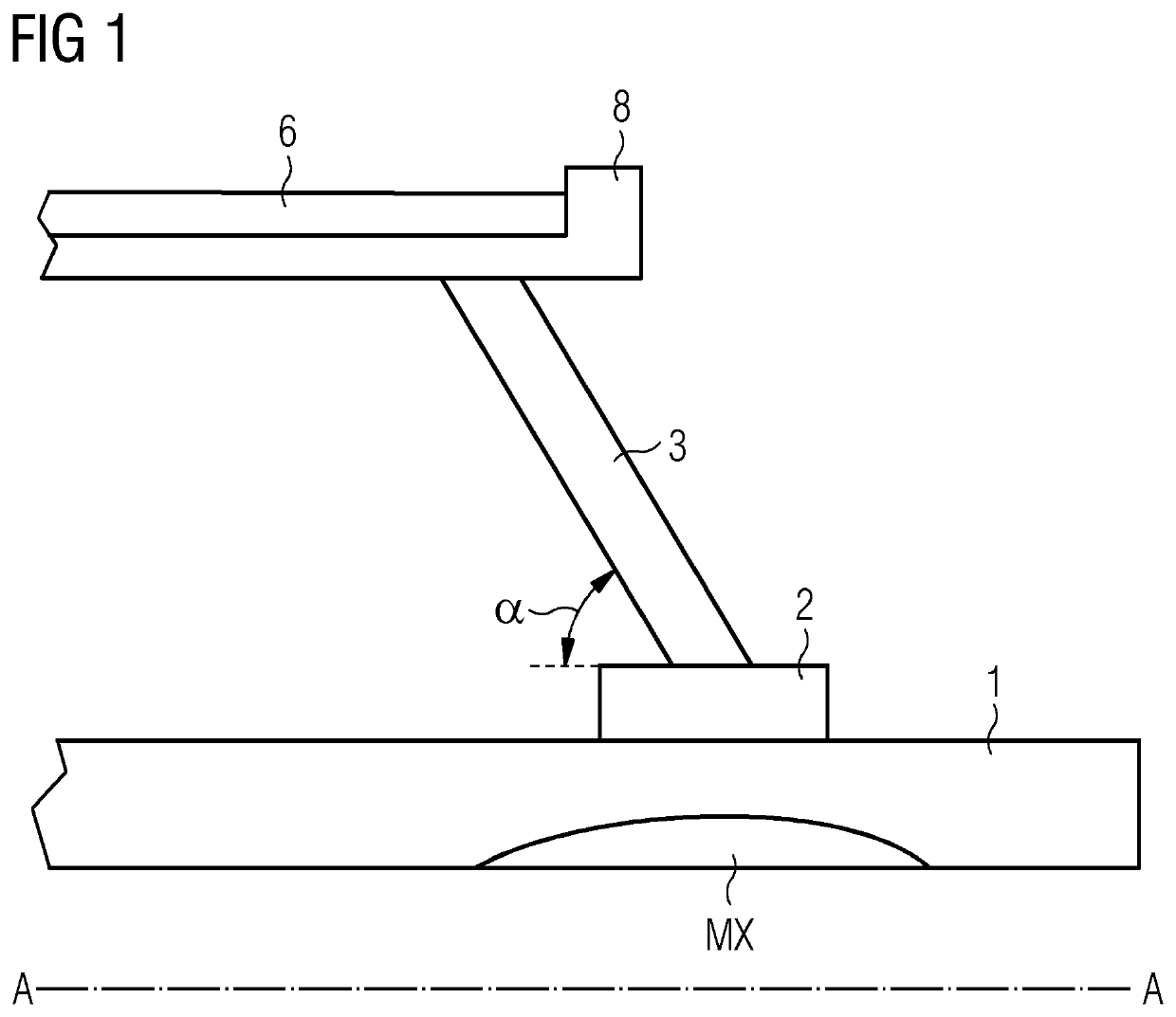
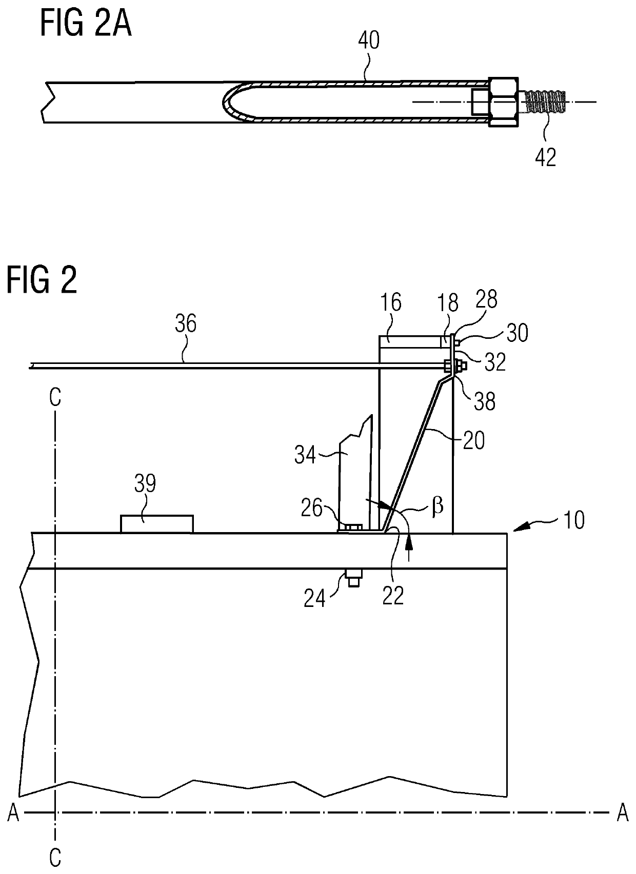
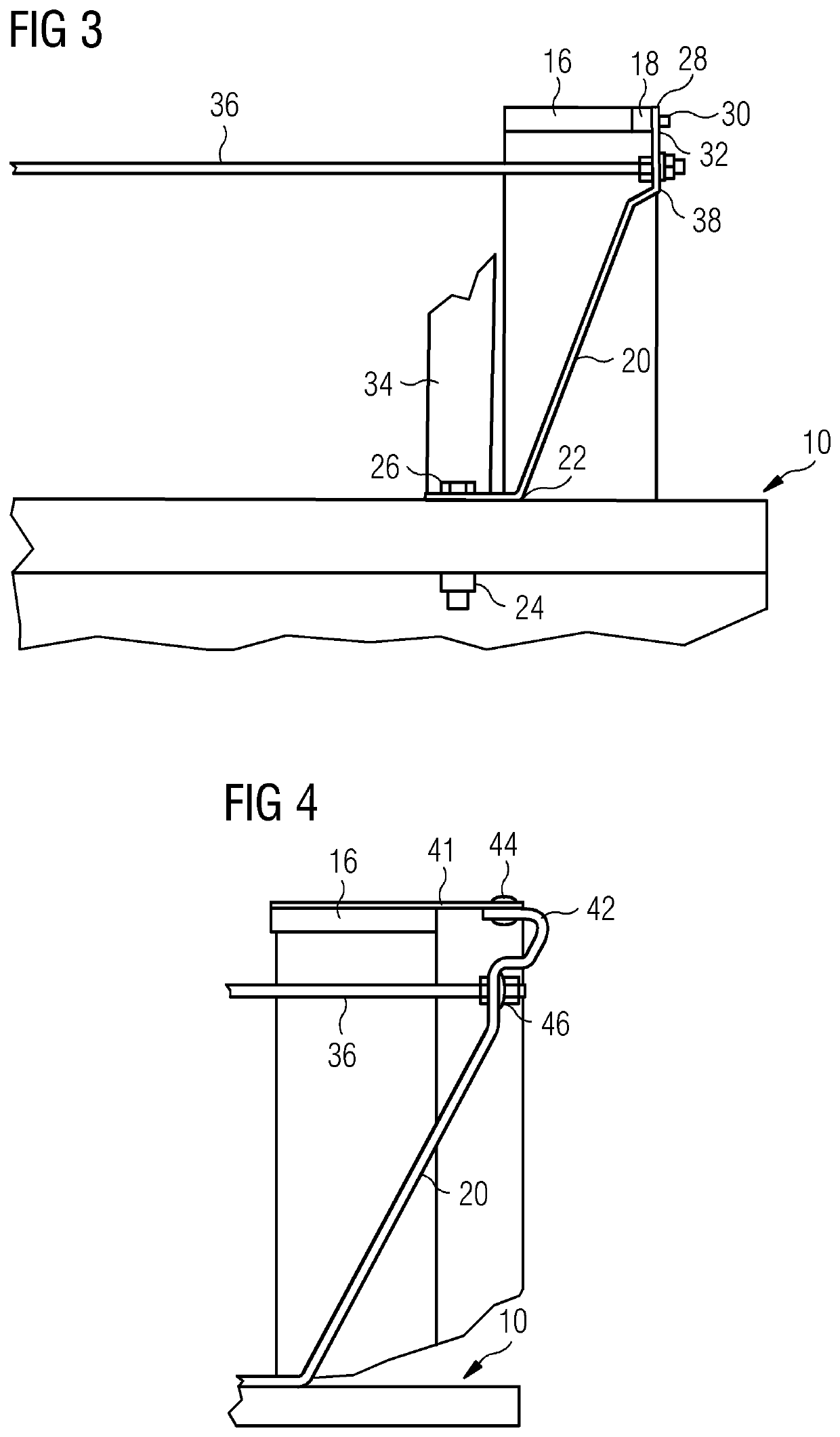
[0015]FIG. 1 shows a conventional superconducting magnet for use in an MRI system, as described in WO2013 / 102509. Self-supporting main magnet assembly 1 may comprise at least one annular superconducting main coil. A number of shield coils 6 of greater diameter than the main coils are provided, pla...


PUM


Abstract

A superconducting magnet assembly may include a main magnet assembly having at least one annular coil arranged about an axis, and at least one shield coil, of greater diameter than the main magnet assembly, arranged about the axis. At least one support may be provided, attached to the shield coil and to the main magnet assembly.

Description

CROSS REFERENCE TO RELATED APPLICATIONS[0001]This is a U.S. National Stage Patent Application of PCT / EP2020 / 070141, filed Jul. 16, 2020, which claims priority to Great Britain (GB) Patent Application No. 1913853.6, filed Sep. 26, 2019. Each of these applications is incorporated herein by reference in its entirety.BACKGROUNDField[0002]The present disclosure relates to superconducting magnets, and in particular to superconducting magnets for use in Magnetic Resonance Imaging (MRI) systems and Nuclear Magnetic Resonance (NMR) systems.Related Art[0003]Typically, such superconducting magnets incorporate active shielding to reduce stray magnetic field. Active shielding comprises counter-running coils positioned outside of the main magnet coils. For an efficient design, there should be a substantial radial gap between the shielding coils and the inner magnet. In operation, the shield coils typically experience axial body forces of many tonnes, and must be accurately positioned. It may be p...

Claims


Application Information

Patent Timeline
IPC IPC(8): G01R33/38G01R33/3815G01R33/385G01R33/421
CPCG01R33/3802G01R33/3804G01R33/3815G01R33/3858G01R33/421H01F6/06H01F6/04
Inventor CALVERT, SIMON JAMES
Owner SIEMENS HEALTHCARE LTD
Learn More