Follower bearing

a follower bearing and bearing technology, applied in the direction of roller bearings, mechanical equipment, rotary machine parts, etc., can solve the problems of bearing deformation and other problems, and achieve the effect of suppressing operating noise, ensuring stable bearing operation, and suppressing damage to other members

Pending Publication Date: 2022-10-27
NIPPON THOMPSON
View PDF6 Cites 0 Cited by
  • Summary
  • Abstract
  • Description
  • Claims
  • Application Information

AI Technical Summary

Benefits of technology

[0007]According to the follower bearing described above, operating noise can be suppressed, damages to other members can be suppressed, and stable operation of the bearing can be ensured.

Problems solved by technology

Further, in the follower bearing, the outer ring may be subjected to a load from the outer circumference side during operation.
In such a case, the bearing may suffer deformation because the outer circumferential surface of the outer ring is covered with resin.

Method used


Image

  • Follower bearing
  • Follower bearing
  • Follower bearing

Examples


embodiment 1

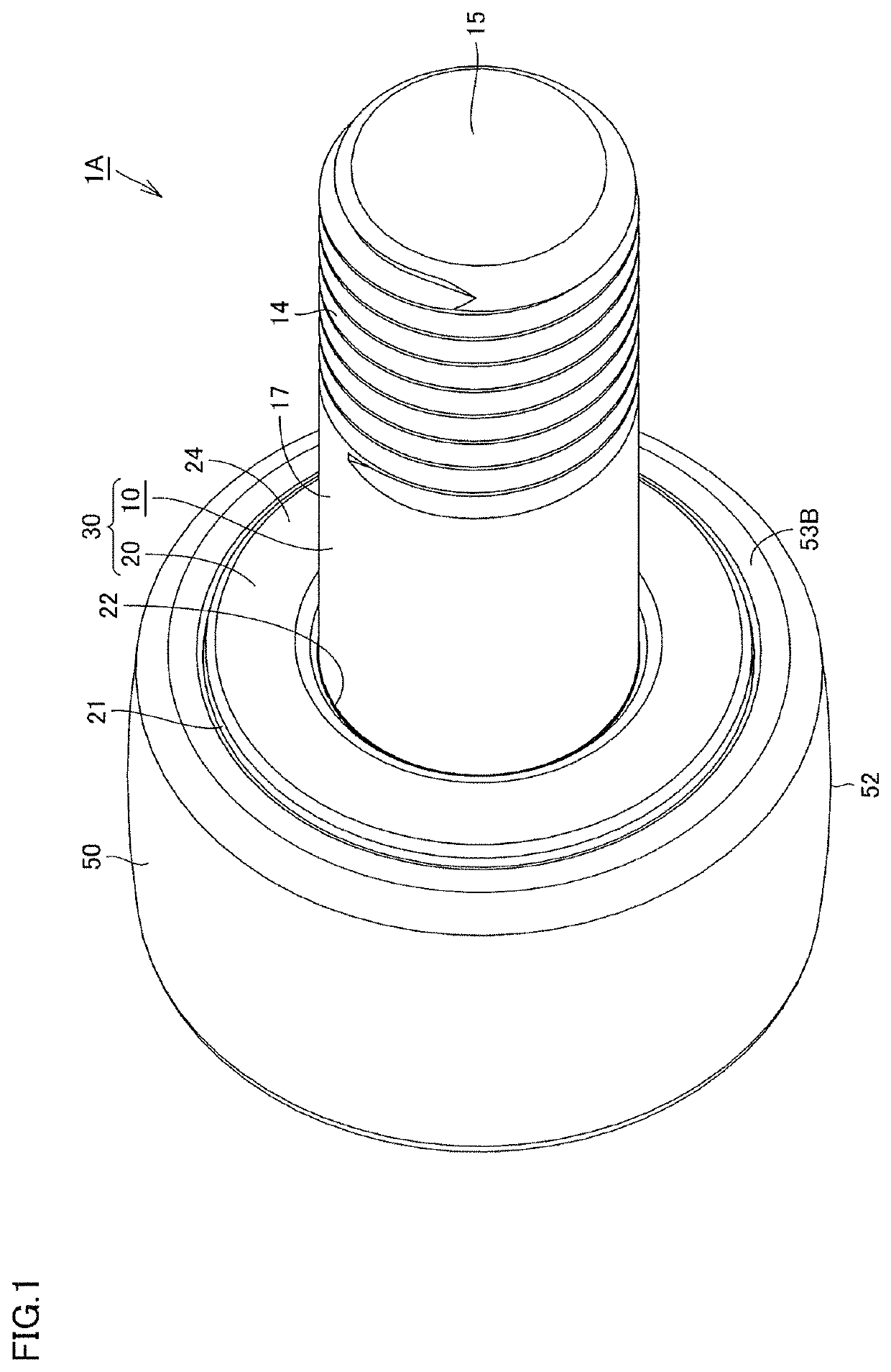
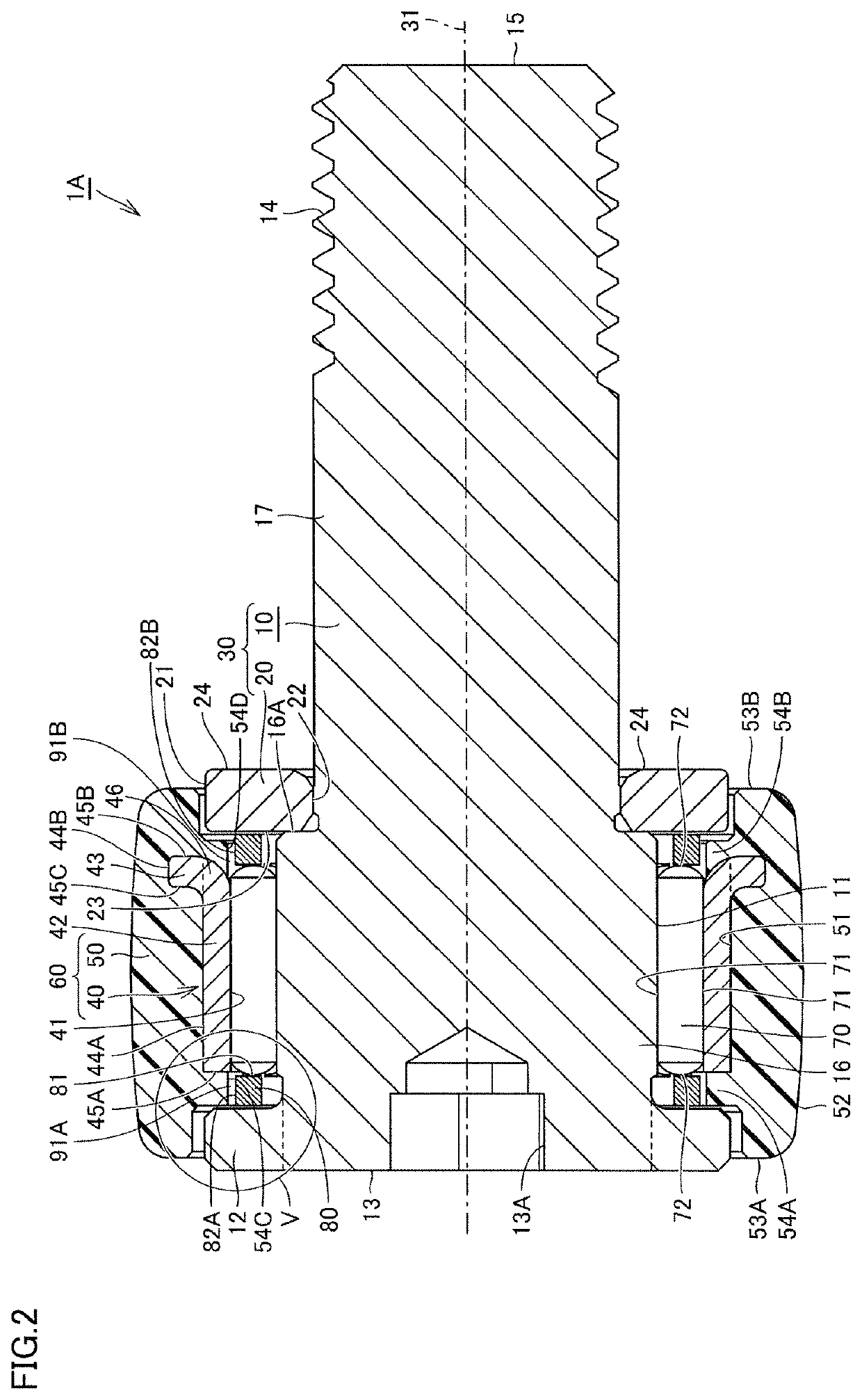
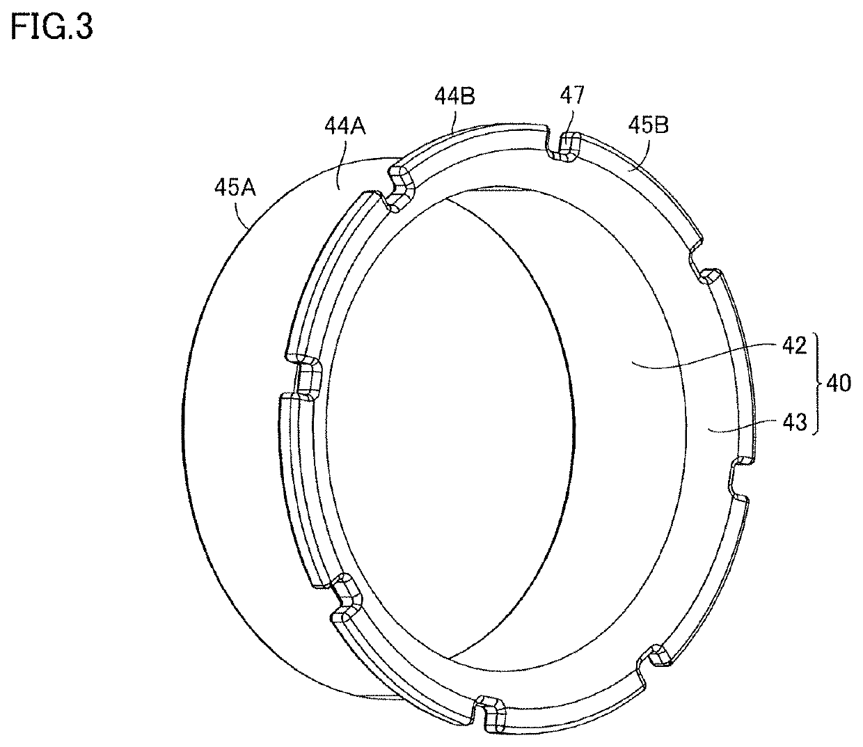
[0043]FIG. 1 is a schematic perspective view showing the structure of a follower bearing as an embodiment of the present disclosure. FIG. 2 is a schematic cross-sectional view showing the structure of the follower bearing shown in FIG. 1. FIG. 2 is a cross-sectional view of the follower bearing when cut in a plane including a rotational axis thereof. FIG. 3 is a schematic perspective view showing the structure of a first member of the outer ring shown in FIG. 1. FIG. 4 is an enlarged schematic cross-sectional view of a portion of the follower bearing shown in FIG. 2. FIG. 5 is an enlarged schematic cross-sectional view of the region V in FIG. 2.

[0044]Referring to FIGS. 1 to 5, the follower bearing 1A in the present embodiment has a shaft member 30 as an inner member, an outer ring 60, a plurality of rollers 70 as rolling elements, and a cage 80 that retains the rollers 70. In FIG. 2, a rotational axis 31, which is the central axis of the shaft member 30, is indicated with a long da...

embodiment 2

[0076]Referring to FIGS. 9 and 10, in a cross section of the follower bearing 1B cut in a plane including its rotational axis, the first opposing surface 54C is inclined with respect to the axial direction such that its distance from the outer circumferential surface 82A of the cage 80 increases from the side closer to the tubular portion 42 to the side farther from the tubular portion 42. Further, in the follower bearing 1B, the first portion 54A includes a tongue-shaped portion 54E that extends to reach a region between the cage 80 and the tubular portion 42. The tongue-shaped portion 54E is formed to extend radially inward. The tongue-shaped portion 54E is formed in a continuous annular shape.

[0077]Here, when a load is applied from the outer circumference side of the outer ring 60, the second member 50, specifically the first portion 54A of the second member 50, is recessed toward the inner circumference side, with a greater deformation amount in the bearing outer region close t...

embodiment 4

[0088]Referring to FIG. 12, the cage 80 included in the follower bearing 1D is a punched cage made of steel. With this configuration as well, stable operation of the bearing can be ensured.

[0089]

[0090]A description will now be made of still yet another embodiment, Embodiment 5. FIG. 13 is a schematic cross-sectional view of a portion of the follower bearing according to Embodiment 5. FIG. 14 is a schematic perspective view of the follower bearing according to Embodiment 5, with the second member omitted from the drawing. The follower bearing of Embodiment 5 differs from that of Embodiment 1 in that the first member is provided with a concave portion as a rotation suppression mechanism to suppress the relative rotation of the second member in the circumferential direction with respect to the first member.

[0091]Referring to FIGS. 13 and 14, the follower bearing 1E according to Embodiment 4 includes, as the rotation suppression mechanism to suppress the relative rotation in the circum...


PUM

PropertyMeasurementUnit
angleaaaaaaaaaa
outer circumference D1aaaaaaaaaa

Abstract

A follower bearing includes an outer ring, rolling elements, and a cage retaining the rolling elements. The outer ring includes an annular first member made of steel, and an annular second member made of resin and covering an outer circumferential surface of the first member. The first member includes a tubular portion. The second member includes a first portion disposed on one side of the tubular portion in an axial direction and having a first opposing surface that opposes an outer circumferential surface of the cage in a radial direction, and a second portion disposed on the other side of the tubular portion in the axial direction and having a second opposing surface that opposes the outer circumferential surface of the cage in the radial direction. In the radial direction, the first and second opposing surfaces are each disposed on a more outer circumference side than a second raceway surface.

Description

BACKGROUND OF THE INVENTION1. Field of the Invention[0001]The present invention relates to a follower bearing.[0002]The present application claims priority based on Japanese Patent Application No. 2021-075088 filed on Apr. 27, 2021, the entire contents of which are incorporated herein by reference.2. Description of the Related Art[0003]A rolling bearing with an outer ring and a pully made of resin integrated into one piece is known (see, for example, Japanese Patent Application Laid-Open No. 2009-191900). According to Japanese Patent Application Laid-Open No. 2009-191900, the outer ring has, at its one end, a flange that faces radially outward. In Japanese Patent Application Laid-Open No. 2009-191900, one end face of the flange in the axial direction is exposed from the resin pulley to improve the heat dissipation of the outer ring.SUMMARY OF THE INVENTION[0004]In a follower bearing, it may be required to suppress operating noise and also to make the bearing less damaging to other m...

Claims


Application Information

Patent Timeline
Patent Type & Authority Applications(United States)
IPC IPC(8): F16H53/06F16C33/58F16C19/06
CPCF16H53/06F16C33/588F16C19/06F16C19/527F16C19/522F16C27/04F16C27/066F16C33/62F16C33/583F16H2055/366F16H55/48F16C19/26F16C33/581F16C13/006F16C2208/10
Inventor NAKAMURA, TOMOAKIKAWASHIMA, TAKAFUMI
Owner NIPPON THOMPSON
Why Eureka
Try Eureka