
Turn signal lamp for outside mirror

a technology for turning signals and outside mirrors, which is applied in the direction of transportation and packaging, semiconductor devices for light sources, lighting and heating apparatus, etc., can solve the problems of poor assembly quality according to fusion distribution, limited security of the size of the turn signal lamp b>1/b>, and a lot of tim

Active Publication Date: 2022-11-03
SMR AUTOMOTIVE MODULES KOREA LTD
View PDF5 Cites 0 Cited by
  • Summary
  • Abstract
  • Description
  • Claims
  • Application Information

AI Technical Summary

Benefits of technology

The patent text describes a new design for a light source unit used in external turn signals for vehicles. By eliminating the need for a separate housing, the design reduces the number of parts and allows for a more compact size. The design also allows for modularization and standardization, improving quality and reducing processing time. Additionally, the design prevents assembly quality issues and defects in the lighting images caused by moisture. Overall, the design provides a more efficient and effective solution for integrating a light source into a vehicle's external turn signals.

Problems solved by technology

Vehicles are equipped with turn signal lamps to inform driving directions or alert conditions through light emission, and a case often occurs in which other drivers do not recognize the turn signal lamp because the turn signal lamps are installed on only the front and rear of a vehicle, resulting in traffic accidents.
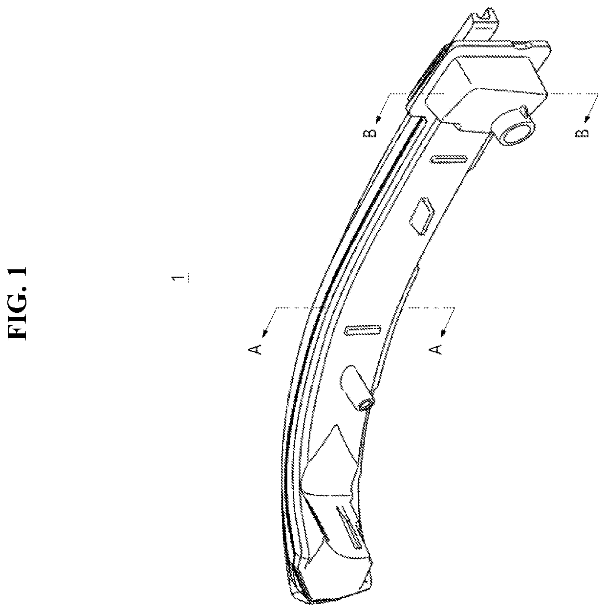
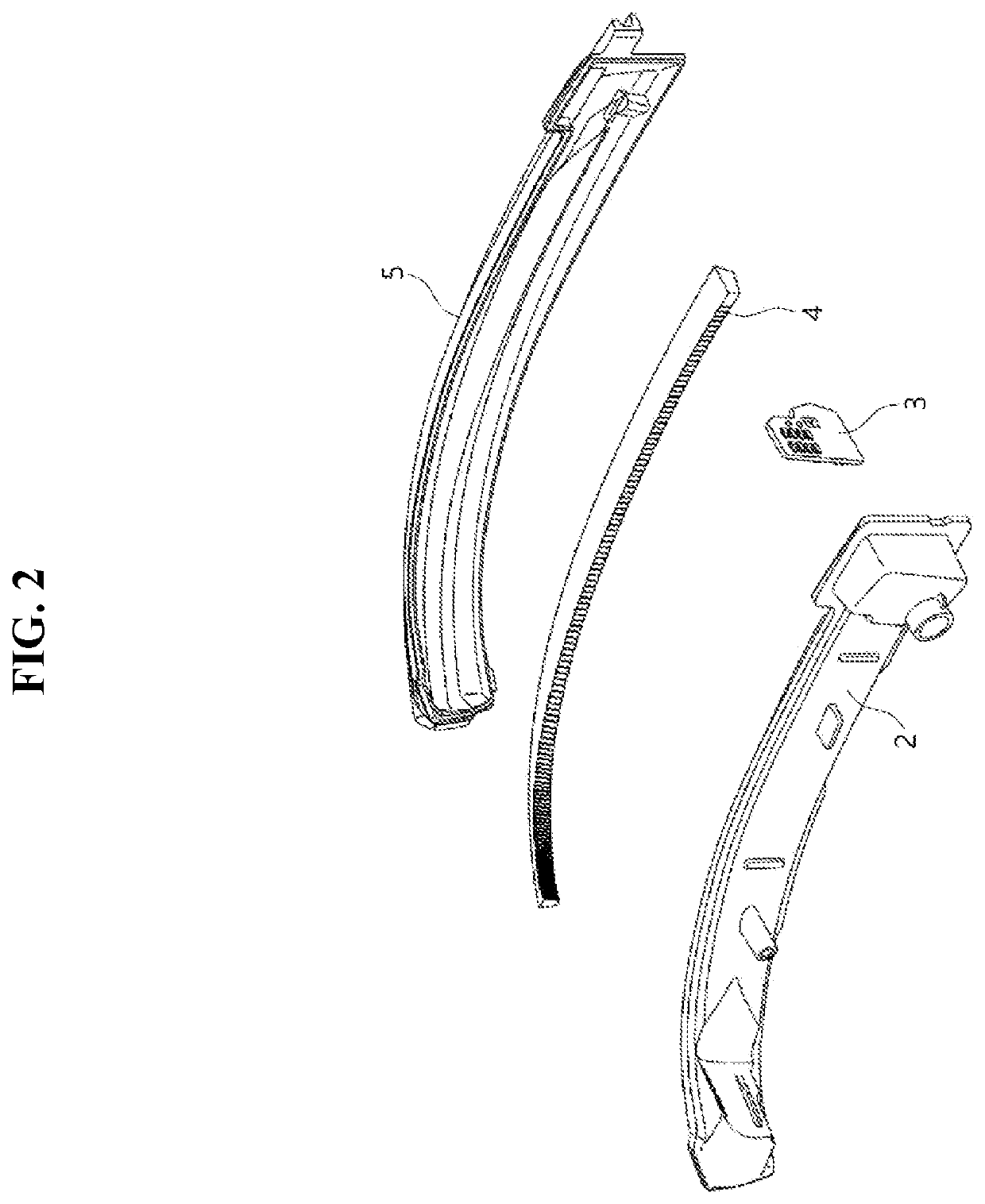
However, in the above-described conventional turn signal lamp 1, a size of the turn signal lamp 1 is limited to secure an assembly space of a light guide 4 and secure a fused surface for fusion of the entire circumference.
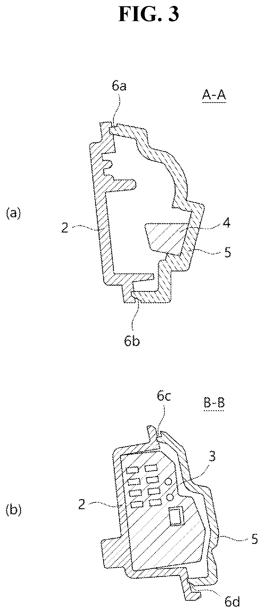
In addition, as shown in FIG. 3A, there is a problem that, due to the existence of a wide fused section such as the housing 2 and the lens 5 being fused even in line A-A, vibration fusion is applied which takes a lot of time, and assembly quality according to a fusion distribution is poor.
In addition, a problem of a lighting image defect occurs because moisture is created in a sealed internal space.

Method used


Image

  • Turn signal lamp for outside mirror
  • Turn signal lamp for outside mirror
  • Turn signal lamp for outside mirror

Examples


Embodiment Construction

[0024]The above-described objects, features, and advantages of the present disclosure will become more apparent from the following detailed description related to the accompanying drawings. However, since the present disclosure may have various changes and may have various embodiments, specific embodiments will be shown in the drawings and described in detail below.

[0025]In the drawings, the thicknesses of layers and regions are exaggerated for clarity, and in addition, when an element or a layer is “on” or “on” another element or layer, this includes all cases in which other elements or layers are interposed therebetween as well as directly on another element or layer. Throughout the specification, the same reference numerals refer to the same elements in principle. In addition, elements having the same function within the scope of the same spirit shown in the drawings of each embodiment will be described using the same reference numerals.

[0026]When it is determined that a detailed...


PUM


Abstract

A turn signal lamp for an outside mirror is disclosed. The turn signal lamp comprises a lens and a light source module coupled to one side of the lens. The light source module includes a printed circuit board (PCB), a PCB assembly including a light emitting diode (LED) disposed on the PCB to output light, and a light source module case configured to accommodate the PCB assembly in an internal space. The light source module case includes a recess formed horizontally along a circumference of a surface of the light source module case. The lens includes a lens protrusion in which a part of the lens protrudes in a shape corresponding to the recess. The lens protrusion is inserted into the recess to come into close contact with a front surface of the recess, so that the light source module and the lens are coupled to each other.

Description

CROSS-REFERENCE TO RELATED APPLICATION[0001]This application claims priority under 35 U.S.C § 119 to Korean Patent Application No. 10-2021-0056880 filed in the Korean Intellectual Property Office on Apr. 30, 2021, the entire contents of which are hereby incorporated by reference.TECHNICAL FIELD[0002]The present disclosure relates to a turn signal lamp for an outside mirror, and more specifically, to a turn signal lamp for an outside mirror, which does not apply a housing to a lens integrally applied with a light guide, thereby reducing the number of parts and solving the limitation to a size of a lamp, and has an appearance with various improved images.RELATED ART[0003]Vehicles are equipped with turn signal lamps to inform driving directions or alert conditions through light emission, and a case often occurs in which other drivers do not recognize the turn signal lamp because the turn signal lamps are installed on only the front and rear of a vehicle, resulting in traffic accidents....

Claims


Application Information

Patent Timeline
IPC IPC(8): B60Q1/26F21S43/14F21S43/245F21S43/27F21S43/19B60R1/12
CPCB60Q1/2665F21S43/14F21S43/245F21S43/27F21S43/19B60R1/1207F21Y2115/10F21W2103/25F21S43/237F21S43/195B60Q1/38B60R1/06F21V15/01F21V23/004F21S43/37F21V17/108F21W2107/10
Inventor LEE, JAE GEUNJUNG, SUNG HOSEO, DONG SUNG
Owner SMR AUTOMOTIVE MODULES KOREA LTD
Learn More