
Radio Frequency (RF) Location Beacon With Tunable Antennas And Cloud Integration

a technology of radio frequency and location beacon, which is applied in the direction of short-range communication service, electrical equipment, transmission, etc., can solve the problems of inability the ability of the defense department's open computer network to communicate with the other military computers on the closed system, and the inability to develop a centralized communication system to be vulnerable to attacks or sabotage, etc., to achieve effective and efficient use of radio frequency wireless communication systems to communica

Active Publication Date: 2022-11-03
APPTRICITY CORP
View PDF18 Cites 0 Cited by
  • Summary
  • Abstract
  • Description
  • Claims
  • Application Information

AI Technical Summary

Benefits of technology

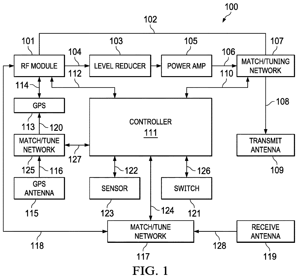
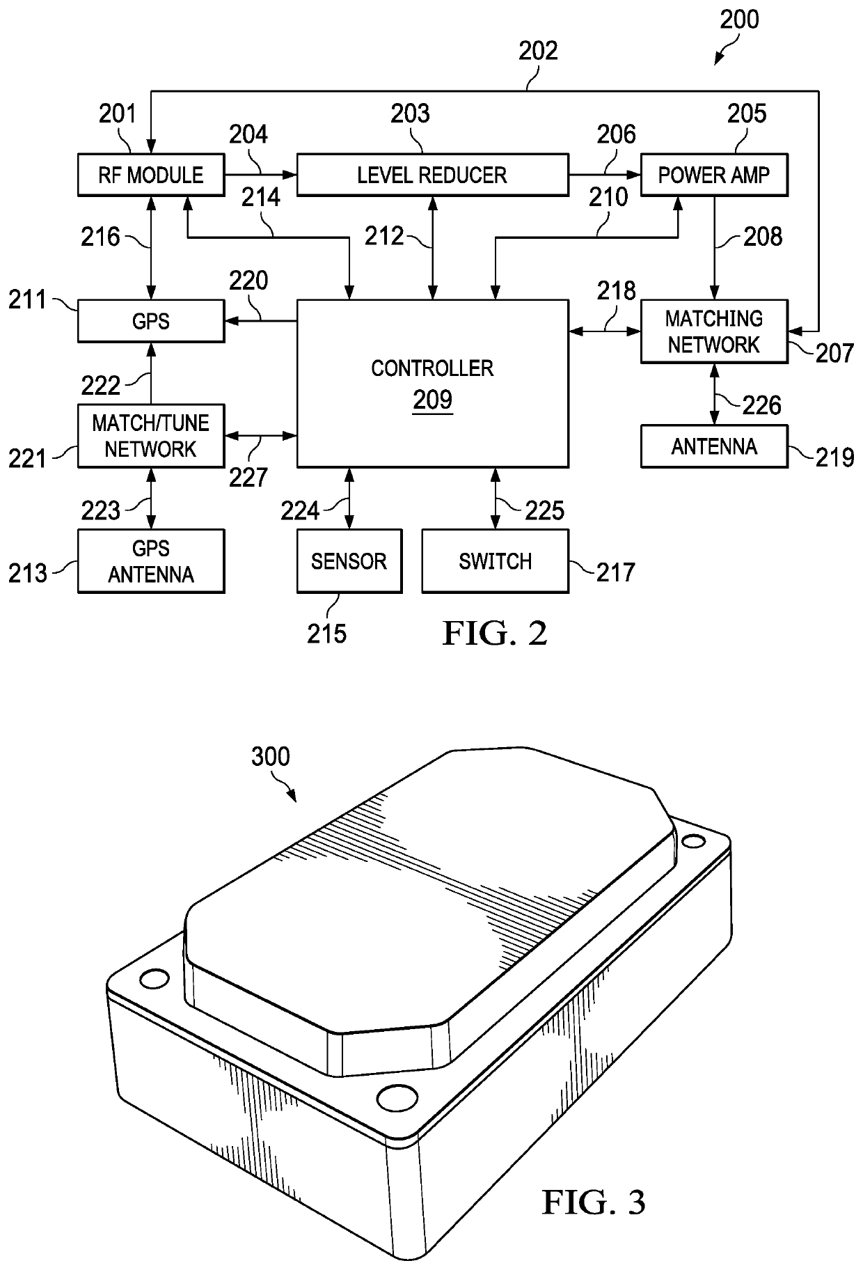
The RF location beacon has the ability to tune the power, efficiency, and sensitivity of its antennas using a controller. This allows the beacon to adjust the range of its signals for transmitting and receiving data. Additionally, the beacon has sensors that use radio signals to transmit and receive data. The technical effect of this is improved efficiency and sensitivity in the transmission and reception of signals, which can aid in the identification and location of objects or people.

Problems solved by technology

Computers on the Defense Department's open computer networks, however, could not communicate with the other military computers on the closed systems.
The Defense Department recognized that developing a centralized communication system would be vulnerable to attacks or sabotage, so the Defense Department required that their new communication system be decentralized with no critical services concentrated in vulnerable failure points.
Prior art communication systems, including the above prior art methods and systems (including known radio frequency wireless communication systems and methods) are not optimized to adequately operate in the mobile environment with efficiency nor do they effectively and efficiently utilize the capabilities of the radio frequency wireless communication systems to communicate and track assets.
However, these active network connections typically carry subscription and data charges.

Method used


Image

  • Radio Frequency (RF) Location Beacon With Tunable Antennas And Cloud Integration
  • Radio Frequency (RF) Location Beacon With Tunable Antennas And Cloud Integration
  • Radio Frequency (RF) Location Beacon With Tunable Antennas And Cloud Integration

Examples


examples

[0135]The following examples represent only a few of the possible uses envisioned for the Radio Frequency Location and / or proximity Beacons of the present invention. These examples are not the only uses of the invention nor is the introduction of these examples intended to in any way limit uses of the invention.

[0136]Building Room Identification: A Radio Frequency Location and / or proximity Beacon can be placed in each room in a building, for example, each room in a hotel or each room in an office, and each beacon has a unique ID that is associated with that room. The receive sensitivity of each beacon unit is tuned such that signals outside of a room are minimized. The transmit power of the unit is set to reach a base station that may be placed in the management center of a hotel or business. Beacon units can then individually, or in concert, signal the location of a RF Radio Module received signal of interest. This could be used, for example, for personnel wearing a radio frequency...


PUM


Abstract

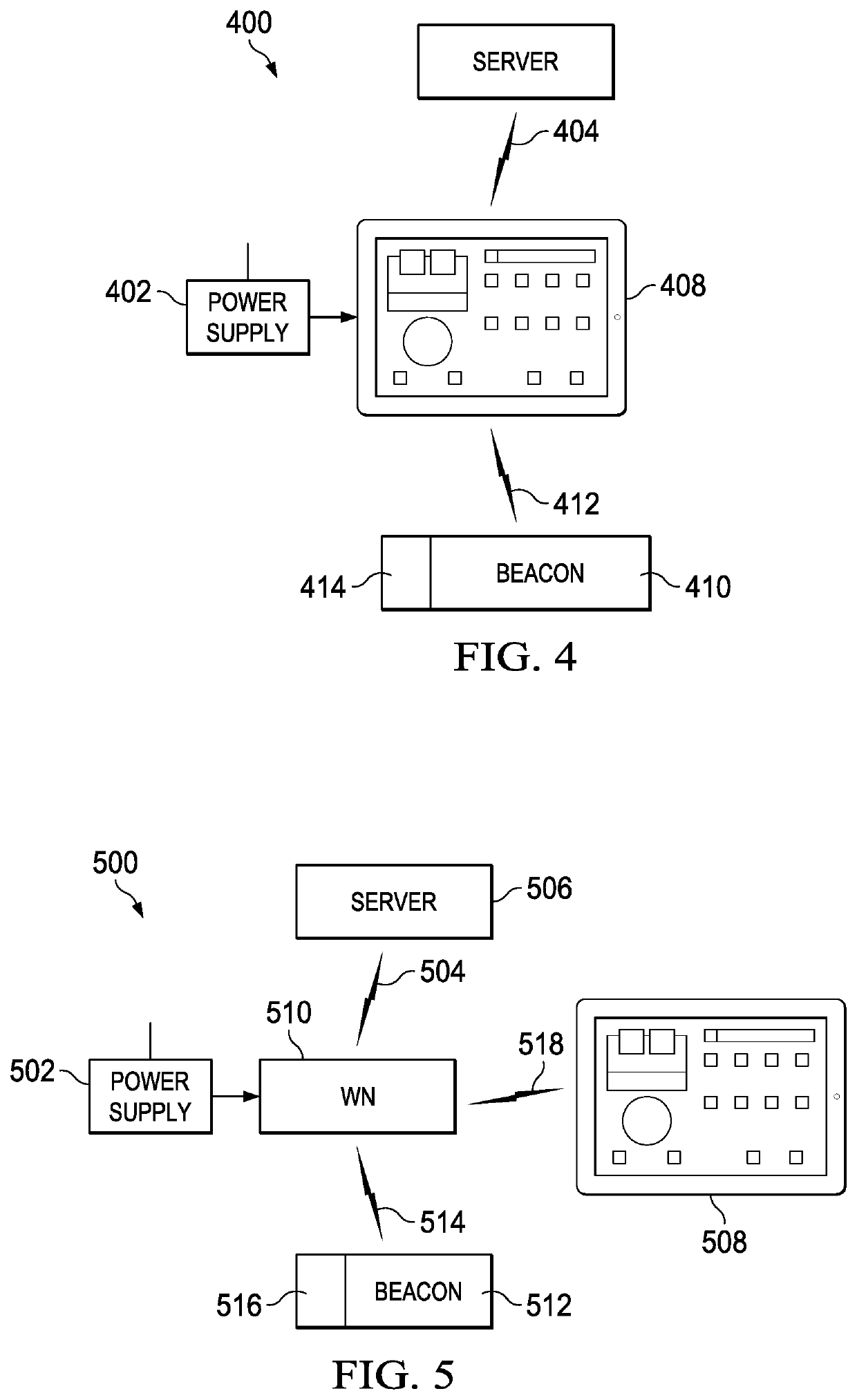
Disclosed herein is a Radio Frequency Location and / or Proximity Beacon receiver / transmitter with one or more tunable antennas and power levels and having the capability for cloud integration. Disclosed herein is a communication system utilizing a Radio Frequency Location and / or Proximity Beacon receiver / transmitter with one or more tunable antennas and power levels and having the capability for cloud integration. The communication system supports processing of communications regarding a radio frequency (RF) beacon for tracking location and / or proximity of field assets. Disclosed herein is a method of using a Radio Frequency Location and / or Proximity Beacon receiver / transmitter with one or more tunable antennas and power levels and having the capability for cloud integration. The method transmits communications regarding a radio frequency beacon for tracking location and / or proximity of field assets.

Description

RELATED APPLICATION DATA[0001]This application claims the benefit of U.S. Provisional Application No. 63 / 006,595, filed Apr. 7, 2020, which is incorporated by reference into this utility patent application.TECHNICAL FIELD OF THE INVENTION[0002]This invention relates to a Radio Frequency (RF) beacon with tunable antennas and integration with a cloud-based tracking system.BACKGROUND OF THE INVENTION[0003]Computers and computer networks have transformed the society and the work environment since their introduction in mass to the business community and the consuming public. The impact we see today on the way business is conducted and consumers interact with service providers and product retailers is rooted in the technological developments in the recent past.[0004]Present-day Internet communications represent the synthesis of technical developments begun in the 1960s—the development of a system to support communications between different United States military computer networks, and the...

Claims


Application Information

Patent Timeline
Patent Type & Authority Applications(United States)
IPC IPC(8): H04B1/40
CPCH04B1/40H04B1/401H04W4/80H04W4/029H04W4/023
Inventor HASLAM, MICHAEL E.PENG, WEIMIN
Owner APPTRICITY CORP
Learn More