Movable cotrol module for hydraulic machine with locking feature

a technology of hydraulic machines and control modules, which is applied in the direction of load-engaging elements, construction, transportation and packaging, etc., can solve the problems of obstructing passage, occupying a lot of space inside the cabin, and limiting the space in the control station

Pending Publication Date: 2022-11-10
VOLVO CONSTR EQUIP
View PDF0 Cites 0 Cited by
  • Summary
  • Abstract
  • Description
  • Claims
  • Application Information

AI Technical Summary

Benefits of technology

The purpose of this disclosure is to provide a simple, effective, and affordable solution. This means that the technical effects of the disclosure are to provide a simple and efficient way to address a particular problem or issue. The goal is always to provide a practical and effective solution to make things easier and more cost-effective for users.

Problems solved by technology

Space in the control station is often limited and the control module generally obstructs the passage in and out of the control station.
However, the movement of rotation of the control module as previously described requires a lot of space inside the cabin.
Also, a gas spring usually does not provide enough resistance to safely secure the control module in the work position or in the retracted position.
Consecutively, reliability of the locking provided by a gas spring cannot be guaranteed for all applications of the machine.
However, the control module is not still safely locked in the retracted position: vibrations and movements of the machine during its shipment or its transportation can provoke the control module to move away from its retracted position.
Therefore, functions of the machine cannot be actuated while the control module is retracted position.
Indeed, having the control module in the retracted position means that the functions of the machine are not supposed to be actuated.
So, there is a risk of unwanted actuation of the functions of the machine during that range of motion of the control module.
At last, the arrangement of the sensor on the cam generates difficulties for calibrating the sensor with precision.
Therefore, safety issues arise because activation of the machine while the control module is in the retracted position can cause accidents of people or damage of the machine.

Method used


Image

  • Movable cotrol module for hydraulic machine with locking feature
  • Movable cotrol module for hydraulic machine with locking feature
  • Movable cotrol module for hydraulic machine with locking feature

Examples


first embodiment

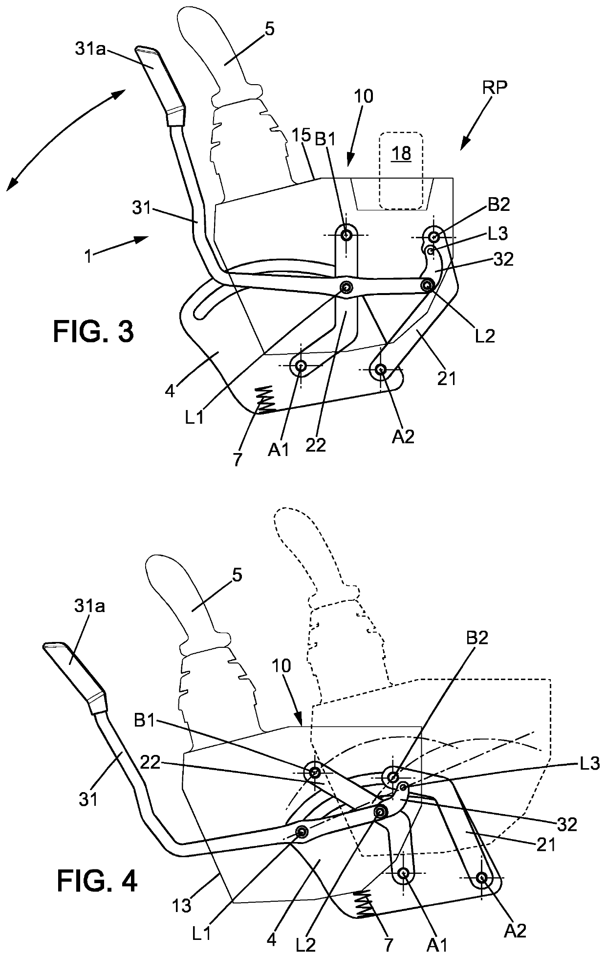
[0088]Referring to FIGS. 2 to 8 concerning the control module 1, the guiding means 20 comprise a second pivotable rod 22. The second pivotable rod 22 is pivotally connected at one end to the support 4 for rotation around a shaft having a transversal axis A1 which is substantially located forward to the transversal axis A2. The second pivotable rod 22 is pivotally connected at a second end to the main body 10 for rotation around a shaft having a transversal axis B1 which substantially located forward to the transversal axis B2. In particular, the second pivotable rod 22 is pivotally connected to the outer wall 12 of the main body 10. The second pivotable rod 22 is then located on the outer side of the outer wall 12 of the main body 10.

second embodiment

[0089]Referring to FIGS. 9 and 10 concerning the control module 1, the guiding means 20 are further made of a second arcuate slot 43 extending longitudinally in the upper portion of the support 4. The second arcuate slot 43 may be positioned above the first arcuate slot 41. The second arcuate slot 43 is intended to cooperate with an inner end of a transversal pin 16 having a transversal axis Cl and mounted on the inner wall 11 of to the main body 10.

[0090]Both embodiments of the guiding means 20 enable moving the main body according to a motion of circular translation. The motion of circular translation maintains a constant orientation of the main body 10 through its all range of motion (which is circular or curved). Consequently, the top surface of the main body 10 remains horizontal during the all range of motion of the main body 10. Therefore, personal belongings or beverages containers can be disposed in the recess 18 of the top surface without being dropped from the top surface...


PUM


Abstract

A control module configured to be part of a control station inside a cabin of a machine: includes a fixed support, a main body movably mounted on the support between a work position and a retracted position, a locking means to lock the main body in the work position, the locking means can be operated between an unlocked state and a locked state in which they keep the main body in its work position The control module also includes an elastic means which is compressed when the locking means are operated between the unlocked state and an intermediate unstable state, and a sensor enabling activation of at least one power circuit of the machine only when the locking means move from the intermediate unstable state to the locked state.

Description

FIELD OF THE INVENTION[0001]The invention relates to a movable control module for a machine (construction equipments, offroad, crane . . . ) with a locking system. This particularly concerns a control module movable between a retracted position and a work position to release a clear passage in and out a cabin of the machine. The invention is also directed to a system to implement such a control module.[0002]The invention also relates to a cabin of a machine equipped with such a control module. This disclosure also relates to a machine equipped with such a control module.BACKGROUND OF THE DISCLOSURE[0003]In the field of machines, such as the ones having hydraulics powered machinery (construction equipments, offroad, crane . . . ), a control module is often provided to a user of the machine to control functions of the machine. Such a control module is commonly part of a control station that is usually located inside a cabin of the machine. The control station often comprises a seat fo...

Claims


Application Information

Patent Timeline
IPC IPC(8): E02F9/20E02F9/16
CPCE02F9/2004E02F9/16E02F3/325B66C13/56
Inventor ARNAL, GREGORYHOUEL, SYLVAINBOND, EDGAR
Owner VOLVO CONSTR EQUIP
Why Eureka
Try Eureka