Method and arrangement for receiving a frequency modulated signal

a frequency modulated signal and receiver technology, applied in the field of frequency modulated signal receiving methods and arrangement, can solve the problems of heterodyne receivers that require more complex receivers, high manufacturing costs, and high power consumption, and achieve the reduction of the effect of reducing the cost of filters, synthesizers and semiconductors, and reducing the number of other discrete components

Inactive Publication Date: 2005-11-08
VIVO MOBILE COMM CO LTD
View PDF17 Cites 0 Cited by
  • Summary
  • Abstract
  • Description
  • Claims
  • Application Information

AI Technical Summary

Benefits of technology

[0006]It is an objective of the invention to provide a simpler and more efficient solution compared to the prior art for receiving a frequency modulated signal, by means of which a good quality of the detected signal can be achieved.
[0019]By means of the invention, the advantages of the direct conversion technique, such as low power consumption, are achieved in the reception of the frequency modulated signal. In addition, the costs of filters, synthesizers and semiconductors, for example, can be substantially reduced. The number of other discrete components can also be reduced. The required components can be advantageously manufactured on an integrated circuit. When implemented in accordance with the invention, the device also requires less space. Besides these advantages, a good quality of the detected signal is achieved. The advantages of the invention can be best utilized in mobile stations and other small, portable receivers, such as pagers.

Problems solved by technology

However, the heterodyne technique requires more complicated receivers, in which the manufacturing costs are higher than in the direct conversion technique, which is becoming more common today.
In addition, power consumption is much higher in a heterodyne receiver than in a receiver implemented with the direct conversion technique.
However, this is too low a frequency to enable an ordinary FM detector to operate as a demodulator with ordinary deviations, such as 8 kHz.
In addition, the conventional LC detector based on a coil and a capacitor cannot be used, because the inductance value of the coil and the capacitance value of the capacitor should be very high.
In addition, FM detectors that operate with the pulse counter principle are known, but even in such a detector, a low intermediate frequency causes a substantial distortion of the detected signal.

Method used


Image

  • Method and arrangement for receiving a frequency modulated signal
  • Method and arrangement for receiving a frequency modulated signal
  • Method and arrangement for receiving a frequency modulated signal

Examples


Embodiment Construction

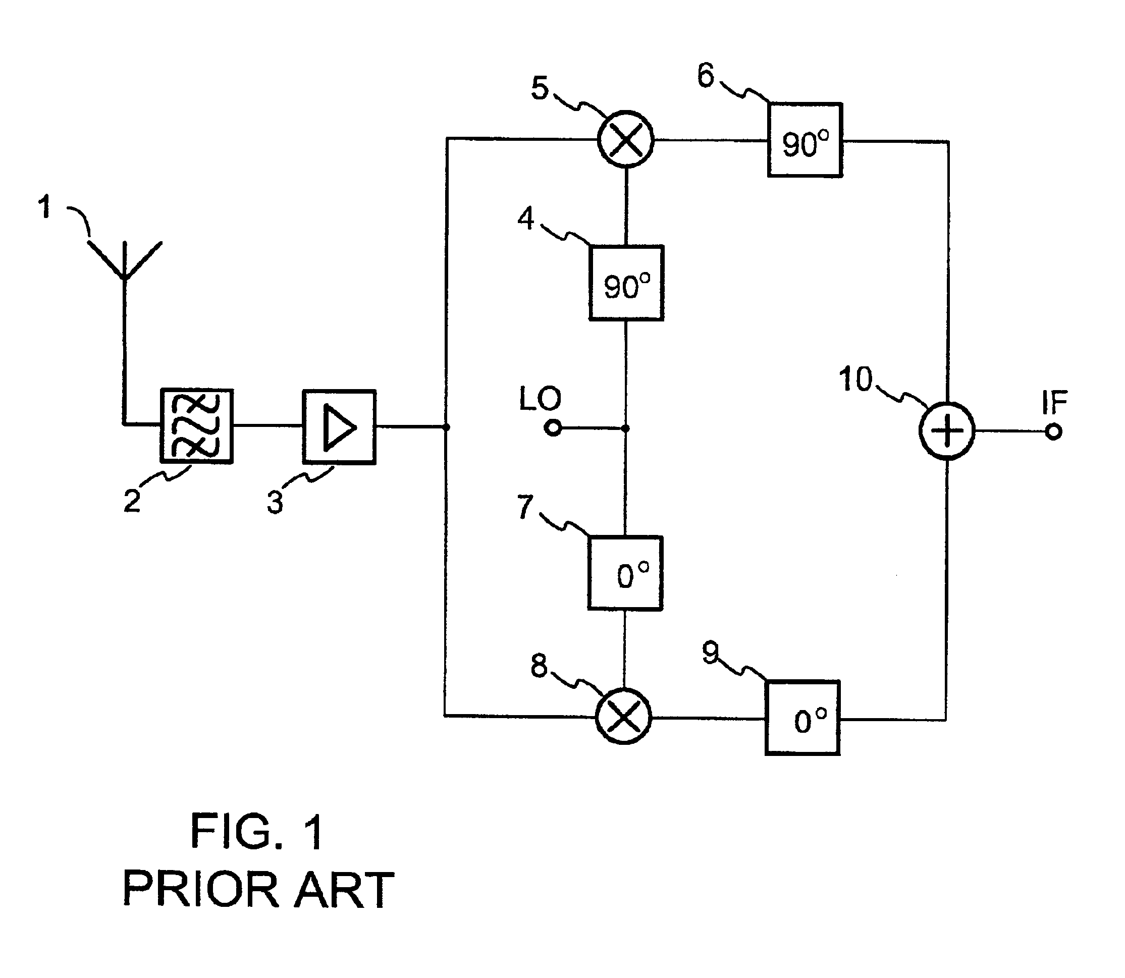
[0027]FIG. 1 was discussed above in connection with the description of the prior art.

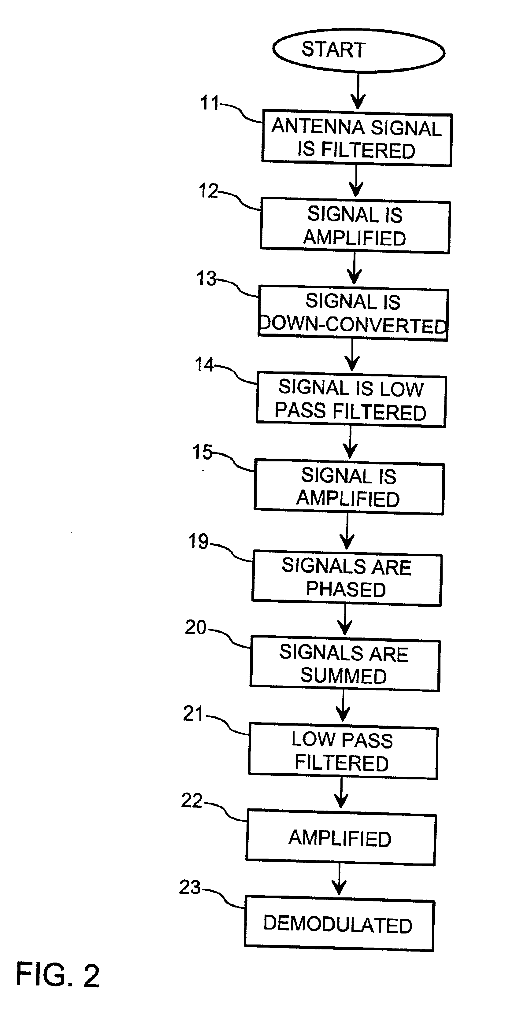
[0028]FIG. 2 shows a flow chart of a method according to the invention for receiving a frequency modulated signal. The signal received by an antenna is filtered 11 with a band pass filter and amplified 12. The amplified signal is down-converted 13 in two branches with 0° and 90° phase-shifted local oscillator signals respectively. The signals of both branches are low pass filtered 14 and amplified 15.

[0029]The frequency modulated signal is processed in accordance with the invention so that the signals are phased 19 in both branches by phase-shifting the signals 0° and 90° respectively. The phase-shifted signals are added 20 into one signal, which is low pass filtered 21, amplified 22 and demodulated 23. The result is a detected low-frequency signal.

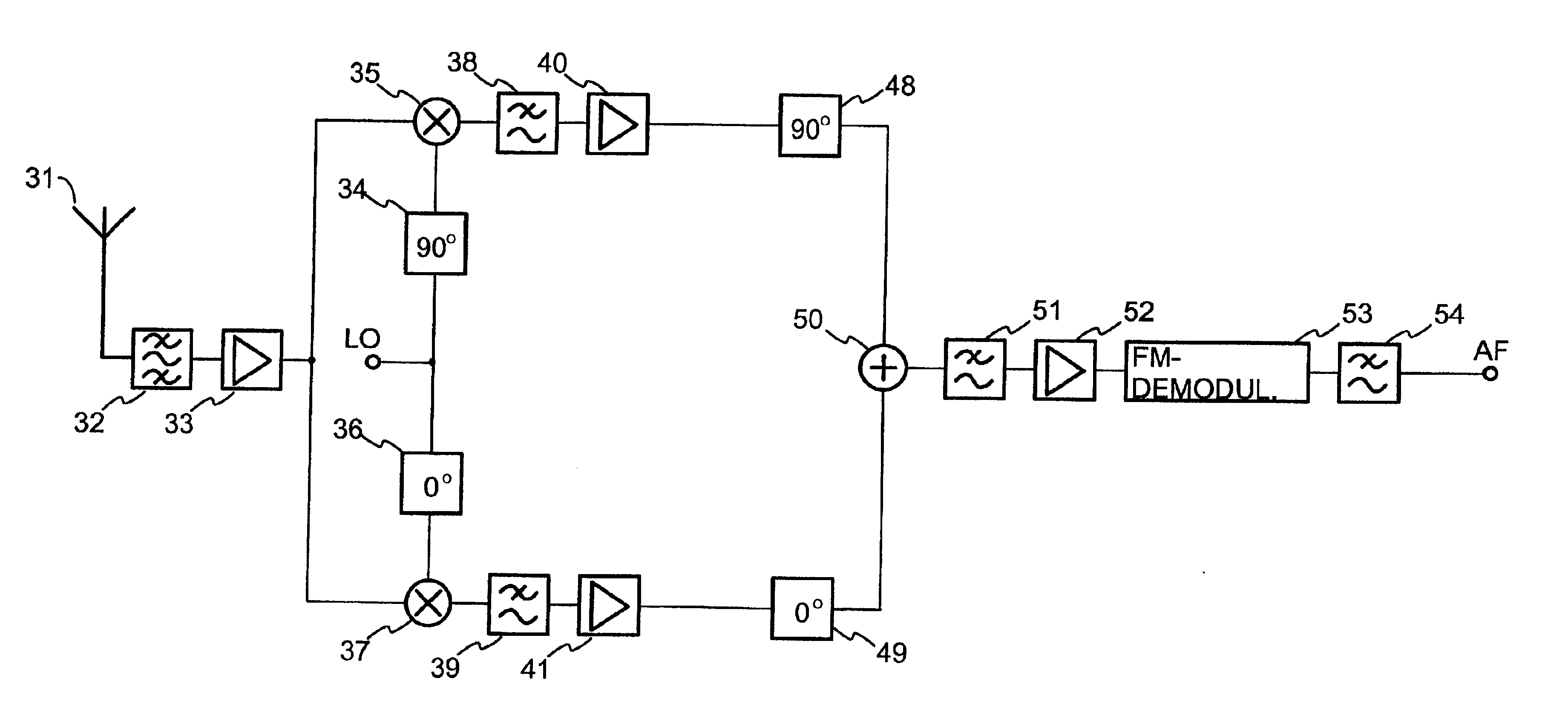
[0030]FIG. 3 shows a block diagram of the parts of a receiver arrangement according to the invention, which are essential for the invention. The signal r...


PUM


Abstract

A method and arrangement for receiving a frequency modulated signal, includes mixing the frequency modulated signal into a low-frequency signal, detecting the falling and rising edges of said low-frequency signal and forming a second signal on the basis of the edge detection, where the frequency of the second signal is twice the frequency of the low-frequency signal, and frequency detecting the second signal to form a demodulated signal.

Description

TECHNICAL FIELD OF THE INVENTION[0001]The invention relates to a method and arrangement for receiving a frequency modulated signal, and especially for demodulating the signal. The invention is applicable especially in the receiver of a mobile station.BACKGROUND ART OF THE INVENTION[0002]Superheterodyne receivers are already known from the prior art. When the superheterodyne technique is used, the radio frequency signal to be received is mixed to a lower frequency by using one or more intermediate frequencies, which are essentially higher than the baseband. However, the heterodyne technique requires more complicated receivers, in which the manufacturing costs are higher than in the direct conversion technique, which is becoming more common today. In addition, power consumption is much higher in a heterodyne receiver than in a receiver implemented with the direct conversion technique. The direct conversion technique or zero intermediate frequency technique means using one frequency mi...

Claims


Application Information

Patent Timeline
IPC IPC(8): H04B1/30
CPCH04B1/30
Inventor VAISANEN, RISTO
Owner VIVO MOBILE COMM CO LTD
Why Eureka
Try Eureka