Splitter plate arrangement for a serrated wind turbine blade

a technology of wind turbine blades and splitters, which is applied in the direction of wind turbines, engine components, wind energy generation, etc., can solve the problems of becoming the source of additional noise, and achieve the effect of improving noise reduction during operation

Active Publication Date: 2021-07-20
LM WP PATENT HLDG
View PDF70 Cites 0 Cited by
  • Summary
  • Abstract
  • Description
  • Claims
  • Application Information

AI Technical Summary

Benefits of technology

[0012]It has been surprisingly found that fitting the relatively thick serration base region with at least one splitter plate is a simple and efficient solution to mitigate the formation and interaction of periodic coherent turbulent structures. These are usually shed from a sufficiently thick trailing edge and may become the source of additional noise. Preferably, the splitter plate is comparatively thin, having a thickness of 2.0 mm or less, more preferably 1.5 mm or less, most preferably 1.0 mm or less.
[0013]Preferably, the splitter plate has a thickness that is less than the thickness of at least part of the adjacent serrations. It has also been found that the noise mitigating effect of the splitter plate arrangement allows for thicker base regions of the serrations. This results in increased design freedom for the serrations and associated material requirements. For instance, less stiff materials, offering edgewise elasticity, which is desired, could be used for the serrations with increased thicknesses, compensating for flexibility in that way. This may reduce material costs in that less costly materials can be used. Also, it increases the robustness of the device, lowering potential maintenance costs, while still maintaining the noise mitigation properties of the arrangement.
[0018]In a preferred embodiment, the splitter plate comprises a vertex, preferably an acute angle vertex, extending into said space in between adjacent serrations. It has been found that such arrangement results in particularly efficient noise mitigation. Advantageously, the acute angle could be substantially identical to the acute angle at the apex of the respective serrations.
[0021]According to a preferred embodiment, said serrations are arranged at incidence to the flow over the wind turbine blade, i.e. at an angle to the flow direction over the blade at the trailing edge of the blade. In one aspect, said serrations are angled towards the pressure side of the wind turbine blade. Preferably, said serrations are angled to the flow direction over the wind turbine blade at an angle of between 0-45 degrees to the flow direction, preferably between 1-25 degrees. This may advantageous increase the lift of the blade.
[0026]According to a preferred embodiment, the splitter plate comprises a parallelogram shaped surface, preferably two opposing parallelogram shaped surfaces. Even more preferred, the splitter plate comprises two opposing diamond shaped surfaces. Thus, both the top surface and the bottom surface of the splitter plate, as separated by a thickness of e.g. less than 2.0 mm, are shaped like a parallelogram or a diamond. This design has the advantage that it enables an easy and efficient attachment of the splitter plates in between adjacent serrations, while the desired noise mitigation is provided.
[0030]According to another embodiment, the splitter plate comprises one or more slits and / or holes, advantageously extending along the height of the serration, e.g. from the distal part of the splitter plate. This embodiment was found to reduce loads on the inventive arrangement, as increased by the added area as compared to prior art serrations. Advantageously, the slits of the splitter plate have a width of 0.2 mm to 2.0 mm.

Problems solved by technology

These are usually shed from a sufficiently thick trailing edge and may become the source of additional noise.

Method used


Image

  • Splitter plate arrangement for a serrated wind turbine blade
  • Splitter plate arrangement for a serrated wind turbine blade
  • Splitter plate arrangement for a serrated wind turbine blade

Examples


Embodiment Construction

[0038]Embodiments of the invention will now be described, by way of example only, with reference to the accompanying drawings, in which:

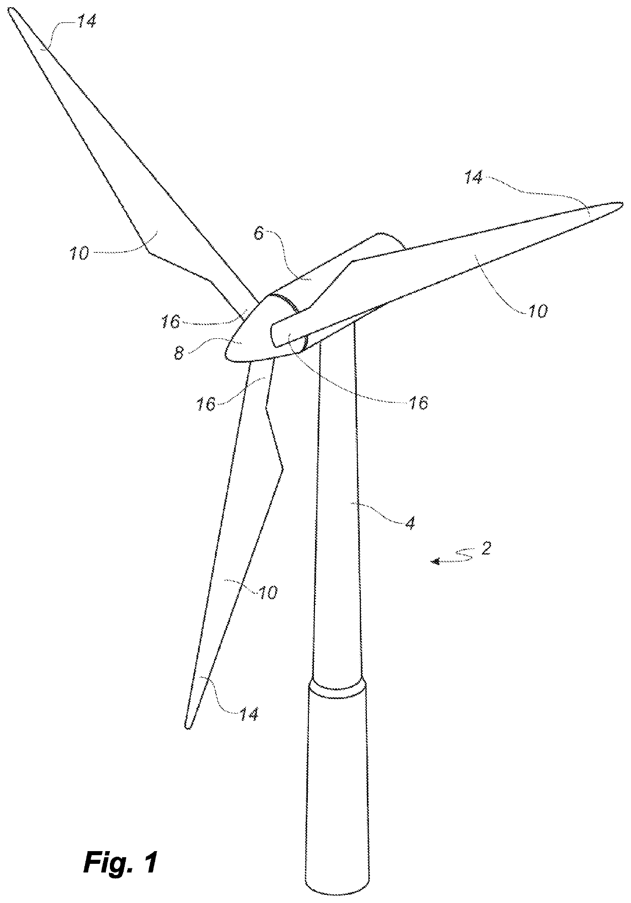
[0039]FIG. 1 shows a wind turbine;

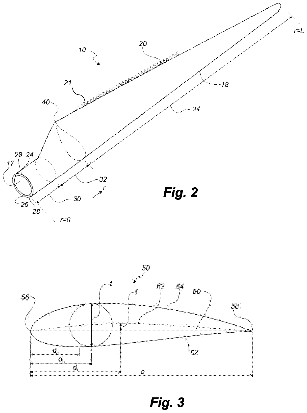
[0040]FIG. 2 shows a schematic view of a wind turbine blade according to the invention;

[0041]FIG. 3 shows a schematic view of an airfoil profile of the blade of FIG. 2;

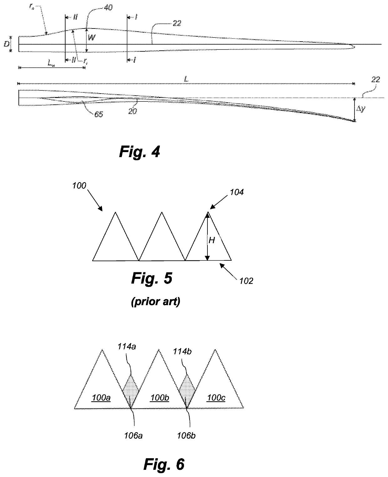
[0042]FIG. 4 shows a schematic view of the wind turbine blade of FIG. 2, seen from above and from the side;

[0043]FIG. 5 illustrates a set of trailing edge serrations;

[0044]FIG. 6 shows a top view of trailing edge serrations and the splitter plate arrangement of the present invention;

[0045]FIG. 7 shows a top view of trailing edge serrations and another embodiment of the splitter plate arrangement of the present invention;

[0046]FIG. 8 shows a perspective partial view of trailing edge serrations and the splitter plate arrangement of the present invention;

[0047]FIG. 9 shows a perspective partial view of trailing edge panel comprising serrations and the sp...


PUM


Abstract

A wind turbine blade (10) is described having a serrated trailing edge (20). Splitter plates (106) are provided on the blade, to reduce operational noise. Each splitter plate (106) is arranged to extend at least partly into a space in between adjacent serrations. The splitter plates can be formed integrally with the serrations, or attached to existing serrations as a retrofit solution. The serrations with the splitter plates can be provided as a trailing edge panel (108) for attachment to the trailing edge of an existing wind turbine blade.

Description

[0001]This is a National Phase Application filed under 35 U.S.C. 371 as a national stage of PCT / EP2016 / 081558, filed Dec. 16, 2016, an application claiming the benefit of European Application No. 15200683.9, filed Dec. 17, 2015, the content of each of which is hereby incorporated by reference in its entirety.FIELD OF THE INVENTION[0002]The present invention relates to a splitter plate arrangement for a wind turbine blade having trailing edge serrations.BACKGROUND OF THE INVENTION[0003]Wind power is increasingly popular due to its clean and environmentally friendly production of energy. The rotor blades of modern wind turbines capture kinetic wind energy by using sophisticated blade design created to maximise efficiency. However, complaints have arisen about the creation of noise associated with the operation of wind power plants. Hence, noise reducing devices and associated blade designs are increasingly desired.[0004]To this end, modern wind turbine blades are sometimes provided wi...

Claims


Application Information

Patent Timeline
Patent Type & Authority Patents(United States)
IPC IPC(8): F03D1/06
CPCF03D1/0675F03D1/0641F05B2240/30F05B2250/183F05B2260/96F05B2280/6003F05B2250/18Y02E10/72
Inventor ARCE, CARLOS
Owner LM WP PATENT HLDG
Why Eureka
Try Eureka