Gait state measurement system, gait state measurement method, and program

a gait state and measurement system technology, applied in gymnastics, instruments, image enhancement, etc., can solve the problems that the relationship between the position of the sole of the trainee and the position of the sensor area cannot be recognized from the outside, and the trainee or the like cannot know, so as to achieve smooth measurement and enhance convenience

Pending Publication Date: 2022-11-17
TOYOTA JIDOSHA KK
View PDF0 Cites 0 Cited by
  • Summary
  • Abstract
  • Description
  • Claims
  • Application Information

AI Technical Summary

Benefits of technology

[0010]The gait state measurement system may include a target area alteration unit that alters at least one of the position, the area, and the shape of the target area based on at least one of attribute information on the subject and an initial position of the sole of the subject. Thus, the gait state measurement system has enhanced convenience and can perform smooth measurement.

Problems solved by technology

Therefore, the relationship between the position of the sole of the trainee and the position of a sensor area cannot be recognized from the outside.
This poses a problem in that, when the sole of the trainee has deviated from a proper position during gait training, such as when the sole has deviated or is about to deviate from the sensor area, the trainee or a therapist or the like cannot know it.

Method used


Image

  • Gait state measurement system, gait state measurement method, and program
  • Gait state measurement system, gait state measurement method, and program
  • Gait state measurement system, gait state measurement method, and program

Examples


embodiment 1

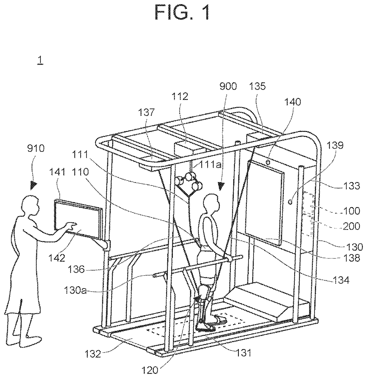
[0034]First, Embodiment 1 of the disclosure will be described. FIG. 1 is a schematic perspective view of a gait training system 1 according to Embodiment 1. The gait training system 1 is one example of a system to which a gait state measurement device (also called a gait state measurement system) according to Embodiment 1 can be applied. The gait training system 1 is a system for a trainee 900 who is a hemiplegia patient suffering from paralysis in one of his or her legs to receive gait training. The trainee 900 is also called a subject. An up-down direction, a left-right direction, and a front-rear direction in the following description are directions based on the directions of the trainee 900.

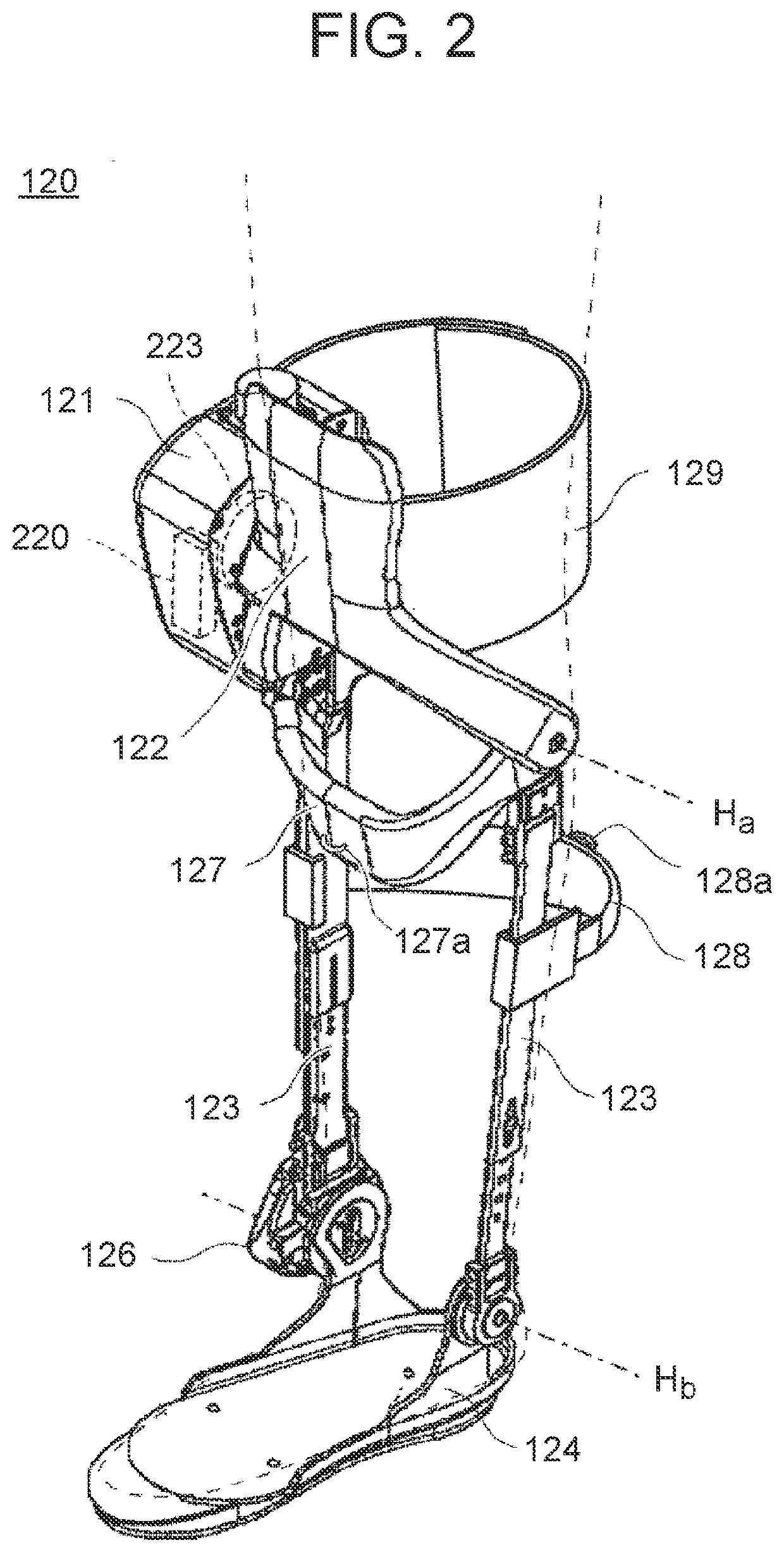
[0035]The gait training system 1 mainly includes a control panel 133 that is mounted on a frame 130 constituting an overall framework, a treadmill 131 on which the trainee 900 walks, and a gait assistive device 120 that is worn on an affected leg that is the leg on the paralyzed side of the t...

embodiment 2

[0094]Next, Embodiment 2 of the disclosure will be described.

[0095]FIG. 9 is a block diagram showing the schematic configuration of a gait state measurement device 100a according to Embodiment 2. In addition to the components and functions of the gait state measurement device 100 according to Embodiment 1, the gait state measurement device 100a according to Embodiment 2 includes a target area alteration unit 107.

[0096]The target area alteration unit 107 sets an initial target area based on the attribute information on the trainee 900 or alters the target area from the initial setting based on the attribute information on the trainee 900. Setting or altering the target area means setting or altering at least one of the position, the area, and the shape of the target area. The attribute information is at least one of information showing which of the left and right legs is the affected leg, the stage of rehab, the length of the leg, the size of the foot, the gender, and the age. Based ...

embodiment 3

[0105]Next, Embodiment 3 of the disclosure will be described. Embodiment 3 is characterized in that the gait state measurement device selects the type of warning and alters the target area based on past and current warnings.

[0106]FIG. 13 is a block diagram showing the schematic configuration of a gait state measurement device 100b according to Embodiment 3. The gait state measurement device 100b according to Embodiment 3 has basically the same components and function as the gait state measurement device 100a according to Embodiment 2. However, the gait state measurement device 100b is different in that it includes a determination unit 103b, a warning control unit 104b, a storage unit 105b, and a target area alteration unit 107b instead of the determination unit 103, the warning control unit 104, the storage unit 105, and the target area alteration unit 107.

[0107]While the determination unit 103b has basically the same functions as the determination unit 103, it functions also as a r...


PUM


Abstract

A gait state measurement device measures a gait state of a subject who is walking on a walking surface formed on a belt that runs along a circulation track. The gait state measurement device includes an acquisition unit, a position estimation unit, and a warning control unit. The acquisition unit acquires measurement information of a load distribution sensor that detects the load of the subject through the belt. The position estimation unit estimates the position of the sole of the subject based on the measurement information. The warning control unit performs a different type of warning depending on a relationship between the position of the sole of the subject and each of target areas that are defined according to an installation area of the load distribution sensor.

Description

CROSS-REFERENCE TO RELATED APPLICATION[0001]This application claims priority to Japanese Patent Application No. 2021-081136 filed on May 12, 2021, incorporated herein by reference in its entirety.BACKGROUND1. Technical Field[0002]The disclosure relates to a gait state measurement system, a gait state measurement method, and a program.2. Description of Related Art[0003]A gait training system for a patient undergoing rehabilitation (hereinafter referred to as rehab) to receive training in walking motion is being developed. In the gait training system, a load distribution of a trainee is measured by a load distribution sensor installed in a treadmill. For example, WO 2006 / 106714 discloses a pressure distribution detection device including two types of loop electrode groups, an elastic body placed on the loop electrode groups, and conductive members placed on the elastic body. The gait training system measures a gait state of the trainee based on a measurement result and assists the tra...

Claims


Application Information

Patent Timeline
Patent Type & Authority Applications(United States)
IPC IPC(8): A61B5/11A61B5/103A61B5/00G06T7/70
CPCA61B5/112A61B5/1036A61B5/74G06T7/70A61B2562/0252G06T2207/30196A63B21/00181A63B21/4001A63B22/02A63B23/04A63B24/0062A63B24/0087A63B2024/009A63B2024/0096A63B2220/805A63B2220/833A63B2230/625A63B2225/20A63B2220/807A63B2220/808A63B2220/89A61B5/103A61B5/6811A61B5/6807
Inventor HAYAKAWA, YOSHINORIMATSUMOTO, TAIGA
Owner TOYOTA JIDOSHA KK
Why Eureka
Try Eureka