
Sample collection device

a collection device and sample technology, applied in the field of sample collection devices, can solve the problems of increasing not only the labor cost, but also the risk of human infection, sample contamination,

Pending Publication Date: 2022-11-17
DELTA ELECTRONICS INC
View PDF0 Cites 0 Cited by
  • Summary
  • Abstract
  • Description
  • Claims
  • Application Information

AI Technical Summary

Benefits of technology

The present disclosure aims to provide a sample collection device that can securely position a sampling swab without being blocked by an external pipet. Additionally, the device has a partitioning member that separates the inner space into two portions for receiving the sampling swab and the external pipet. This also helps prevent misplacing of the sampling swab.

Problems solved by technology

Because the sampling swab is placed in the sample collection device in a random angle, the entering of the pipet is easily blocked thereby, which results in that the operator has to adjust the position of the sampling swab manually for ensuring a smooth entering of the pipet.
When the pipet of the automated apparatus enters the sample collection device, the problem described above also occurs and causes an interruption of the automated procedure due to being blocked by the sampling swab.
Accordingly, an additional step of manually adjusting or removing the sampling swab needs to be added before starting the automated procedure, which increases not only the labor cost, but also the risks of sample contamination and human infection.

Method used


Image

  • Sample collection device
  • Sample collection device
  • Sample collection device

Examples


Embodiment Construction

[0034]The present disclosure will now be described more specifically with reference to the following embodiments. It is to be noted that the following descriptions of preferred embodiments of this disclosure are presented herein for purpose of illustration and description only. It is not intended to be exhaustive or to be limited to the precise form disclosed.

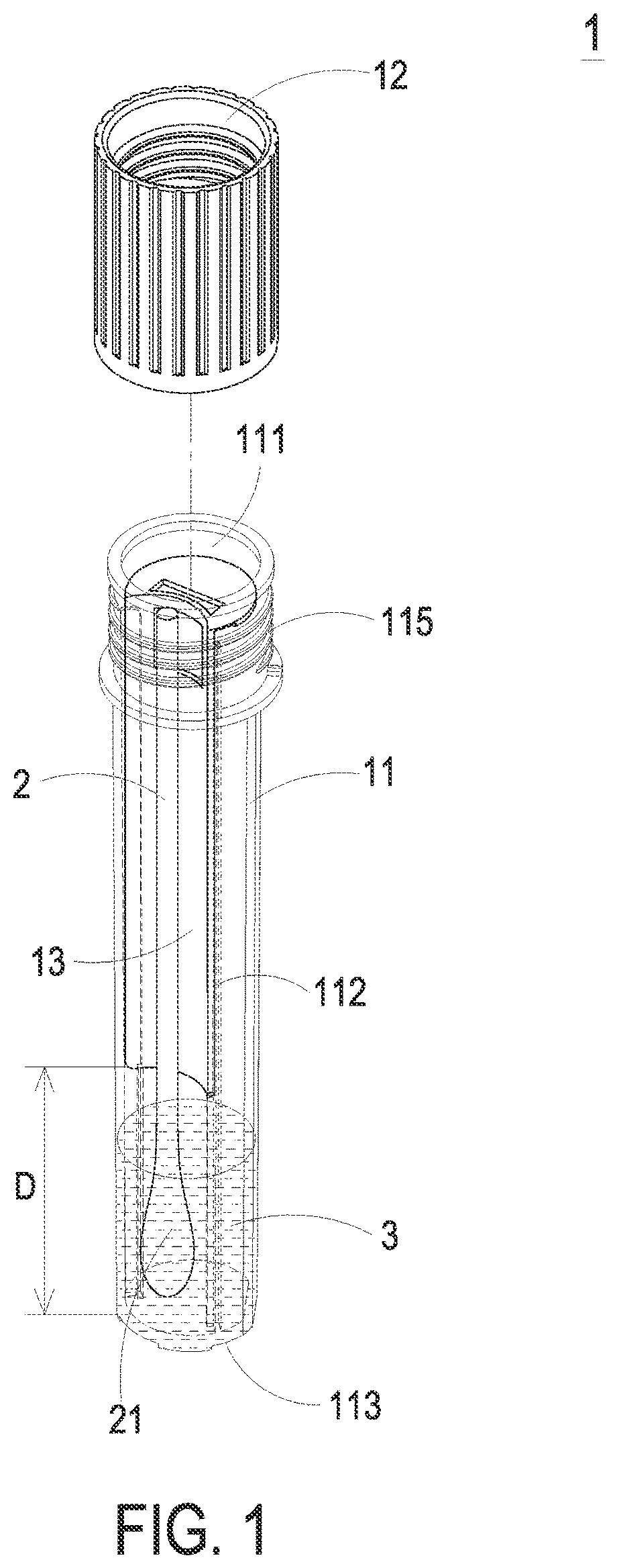
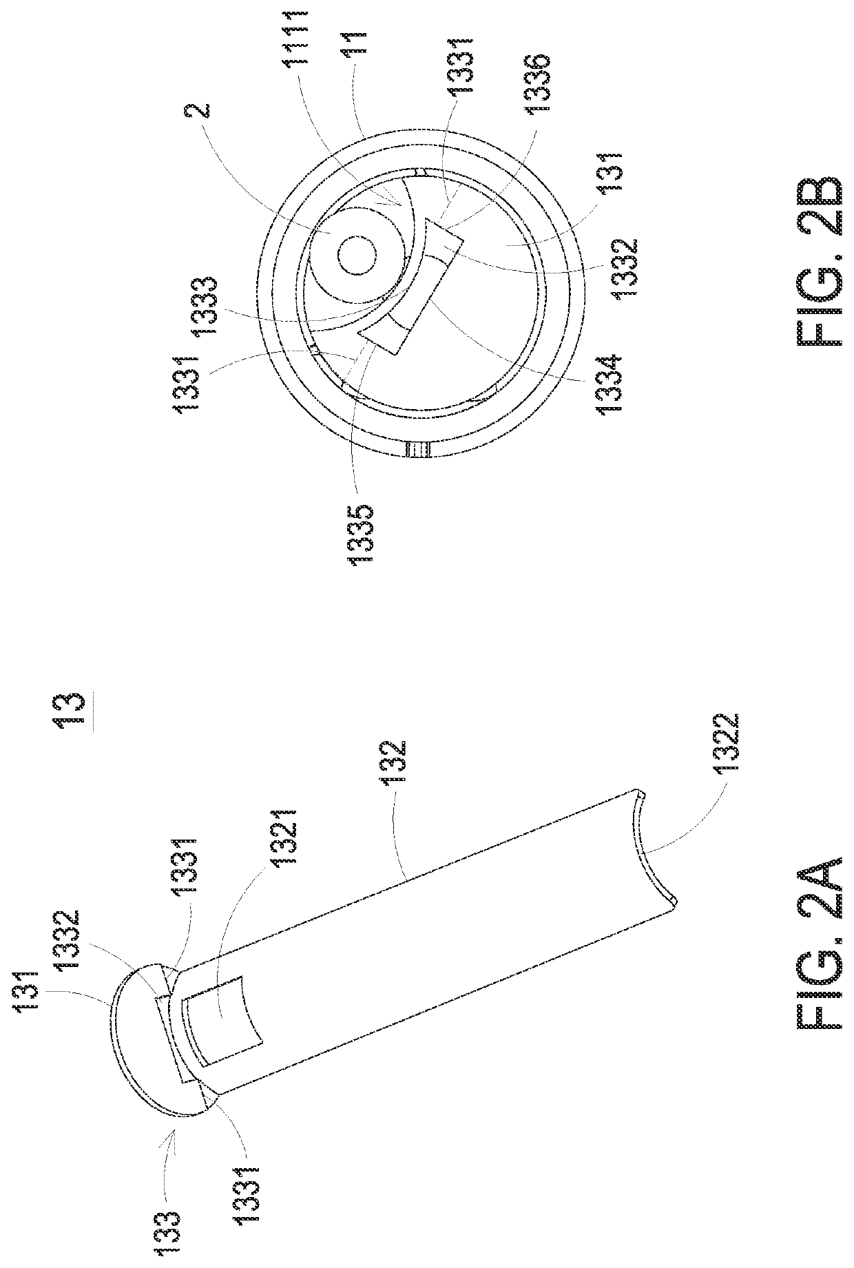
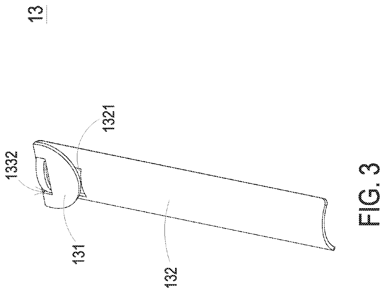
[0035]Please refer to FIG. 1, which is a schematic view showing a sample collection device according to an embodiment of the present disclosure. A sample collection device 1 includes a tube 11, a closure 12 and a partitioning member 13. The tube 11 has an opening 111, and a sampling swab 2 (such as a flocked swab or a cotton swab) can pass through the opening 111 and be received in the tube 11. The closure 12 is engaged with the tube 11 for enclosing the opening 111, so as to keep the sampling swab 2 in the tube 11, prevent the liquid 3 (e.g., sample preservation liquid) in the tube 11 from leaking out, and avoid sample contami...


PUM

PropertyMeasurementUnit
lengthaaaaaaaaaa
cylindrical shapeaaaaaaaaaa
shapeaaaaaaaaaa

Abstract

A sample collection device includes a tube, a closure and a partitioning member. The tube includes an opening and is used to receive a sampling swab. The closure is engaged with the tube for enclosing the opening. The partitioning member is disposed in the tube and includes a blocking portion and a position-limiting portion. The blocking portion is disposed close to the opening and covers a portion of the opening so as to leave another uncovered portion as an entrance for passing the sampling swab therethrough. The position-limiting portion is connected with the blocking portion and extended into the tube, so as to limit the sampling swab in a space corresponding to the entrance inside the tube after the sampling swab passes through the entrance.

Description

CROSS-REFERENCE TO RELATED APPLICATION[0001]This application claims the benefit of U.S. Provisional Application No. 63 / 188,746 filed on May 14, 2021 and entitled “AUTOMATIC NUCLEIC ACID PROCESSING WORKSTATION”. This application also claims priority to China Patent Application No. 202210290795.9 filed on Mar. 23, 2022. The entireties of the above-mentioned patent application are incorporated herein by reference for all purposes.FIELD OF THE INVENTION[0002]The present disclosure relates to a sample collection device, and more particularly to a sample collection device suitable for an automated apparatus.BACKGROUND OF THE INVENTION[0003]The detections of many diseases (such as respiratory diseases, reproductive tract diseases, urinary tract diseases, and other related diseases) are sampled via a sampling swab, e.g., a flocked swab or a cotton swab. After sampling, the sampling swab is put into a sample collection device, so that the head portion of the sampling swab can be immersed in ...

Claims


Application Information

Patent Timeline
Patent Type & Authority Applications(United States)
IPC IPC(8): B01L3/00A61B10/00G01N1/02
CPCB01L3/5029A61B10/0045A61B10/0096G01N1/02G01N2001/028B01L2300/0832B65D41/04C12M23/06C12M23/34C12M23/38C12M33/04B01L3/50853B01L2300/042B01L2300/0609B01L2300/0858B03C1/01B03C1/284B03C1/286B03C2201/18B03C2201/26Y02A50/30Y02W90/10B01L3/0227B01L3/0234B01L7/52B01L2300/021B01L2300/0829B01L2300/1805B03C1/288G01N35/0098G01N35/1002
Inventor HUANG, SONG-BINGENG, JINGLONG, QUANKEZHAO, XIAOZHICHANG, HSIU-HUI
Owner DELTA ELECTRONICS INC
Learn More