Casting pouring gate structure of hub

A wheel hub and sprue bushing technology, which is applied in the direction of casting molding equipment, casting molds, casting mold components, etc., can solve the problems of affecting the filtering effect of the filter, slag inclusion, air leakage, drawing the mold, and the leveling of the filter, so as to reduce the scrap rate , Improve product quality, ensure the effect of filtering effect

Inactive Publication Date: 2014-03-26
TIANJIN DAIKA WHEEL HUB MFG
View PDF4 Cites 6 Cited by
  • Summary
  • Abstract
  • Description
  • Claims
  • Application Information

AI Technical Summary

Problems solved by technology

[0003] Aluminum alloy wheel blanks are produced by low-pressure casting. During casting, as attached Figures 1 to 2 As shown, the sprue sleeve 2 needs to be coaxially installed on the upper end of the sprue cup 3, and the cylindrical filter 1 is installed in the sprue sleeve. An inverted conical through-hole with an upper diameter larger than the lower end diameter is coaxially formed in the sprue sleeve. The diameter of the lower end of the through hole is the same as the diameter of the cylindrical filter, and the lower edge of the filter is flush with the lower end of the sprue sleeve, but it is easy to remain at the riser where the sprue sleeve and the inner wall of the sprue cup are connected. Aluminum block 4, the lower edge of the filter screen cannot be flush with the lower end of the sprue sleeve, resulting in a gap between the filter screen and the inner wall of the sprue sleeve, affecting the filtering effect of the filter screen, and even causing problems such as slag inclusion, air leakage, and die drawing. cause waste

Method used


Image

  • Casting pouring gate structure of hub
  • Casting pouring gate structure of hub
  • Casting pouring gate structure of hub

Examples


Embodiment Construction

[0021] The present invention will be further described in detail below in conjunction with the accompanying drawings and through specific embodiments. The following embodiments are only descriptive, not restrictive, and cannot limit the protection scope of the present invention.

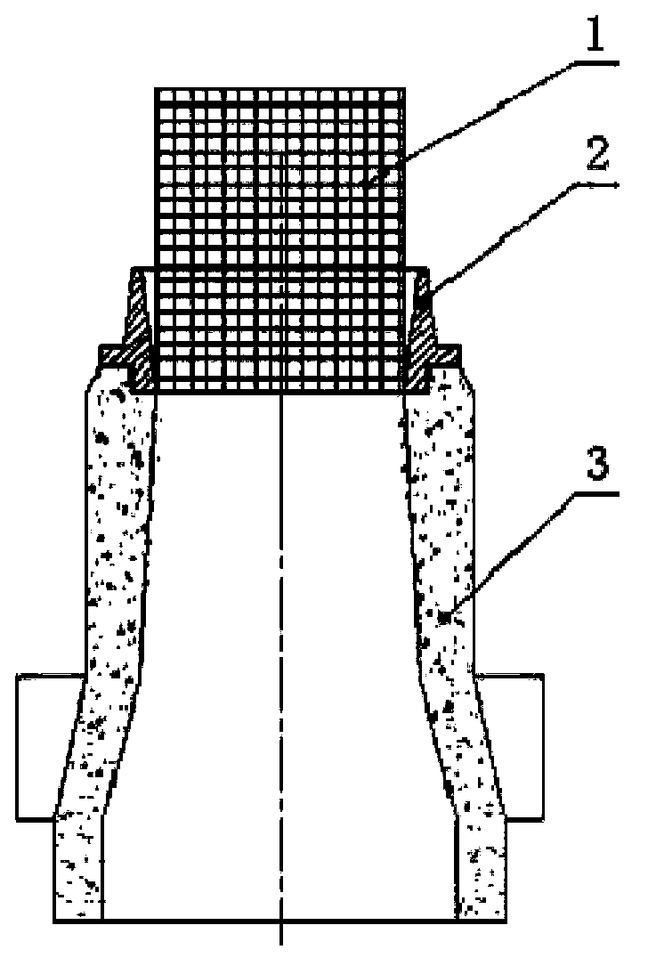
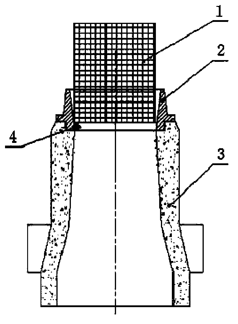
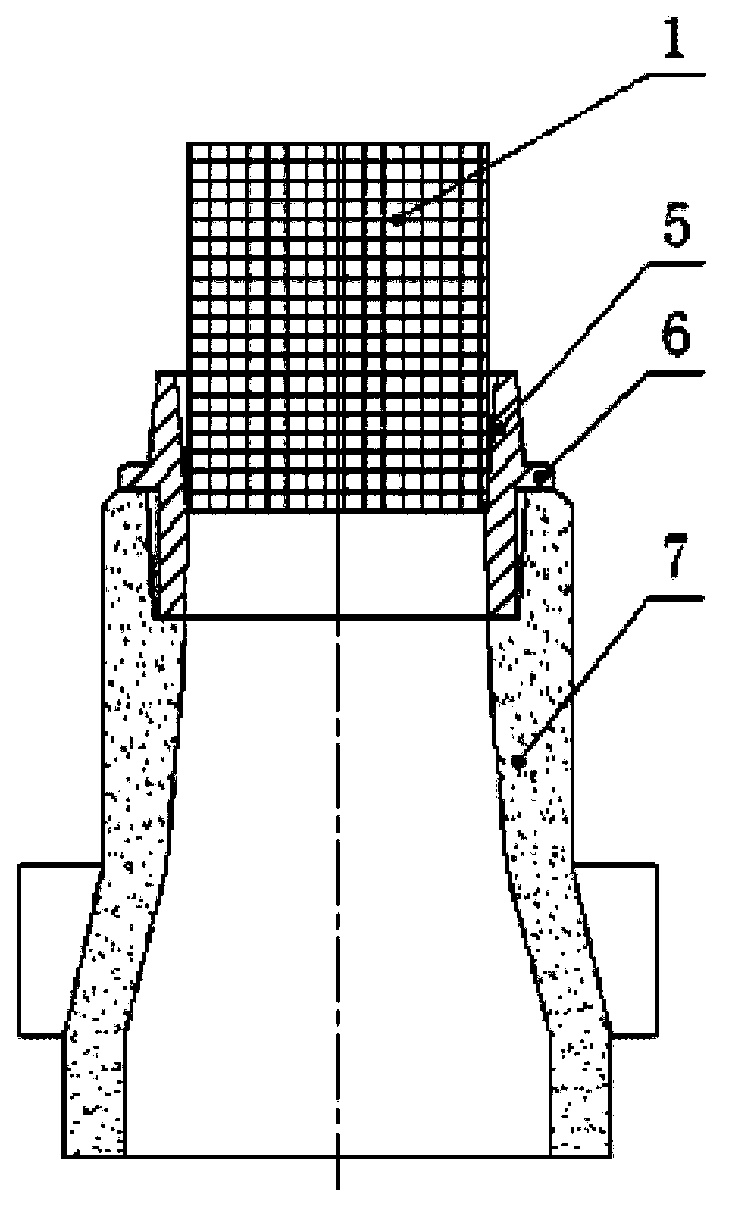
[0022] A hub casting gate structure, such as Figures 3 to 4 As shown, the sprue cup 7, the sprue sleeve 5 and the cylindrical filter screen 1 are included, the sprue sleeve is coaxially embedded at the upper end of the sprue cup, and the filter screen is coaxially installed in the sprue sleeve. The innovation of the present invention is :

[0023] The sprue sleeve is in the shape of a cylinder, and a coaxial through hole is formed in the cylinder, the diameter of the upper end of the through hole is greater than the diameter of the cylindrical filter, and the diameter of the middle part of the through hole is the same as the diameter of the cylindrical filter. , the diameter from the middle of the ...


PUM


Abstract

The invention relates to a casting pouring gate structure of a hub. The casting pouring gate structure comprises a pouring cup, a sprue bush and a cylindrical filter screen, wherein the upper part of the pouring cup is coaxially provided with an annular mounting groove matched with the sprue bush; the annular mounting groove is internally coaxially embedded with the sprue bush, the sprue bush is internally coaxially provided with the filter screen and is of a cylinder shape; the cylinder shape is internally coaxially provided with a through hole, the diameter of the upper end of the through hole is greater than that of the cylindrical filter screen, the diameter of the middle of the through hole is the same as that of the cylindrical filter screen, the hole diameters from the middle of the through hole to the lower end of the through hole are same, and the lower edge of the cylindrical filter screen is arranged in the middle of the sprue bush. The casting pouring gate structure provided by the invention has the advantages that a residual aluminium block arranged at a dead head is far from the lower edge of the filter screen, the problem that the placement of the filter screen is not exact because of the residual aluminium block at the dead head is effectively avoided, the filtering effect of the filter screen is effectively guaranteed, a condition that wastes such as slag inclusion air leakage drawplates are generated because of the filter screen placing problem is effectively avoided, the rejection rate of a product is effectively reduced, the product quality is improved, and the production cost is reduced.

Description

technical field [0001] The invention belongs to the field of wheel hub casting, in particular to a wheel hub casting gate structure. Background technique [0002] The wheel hub is an important part of the car, which has a great influence on the overall performance of the vehicle. The alloy wheel hub has the advantages of light weight, small inertial resistance, high manufacturing precision, and good heat dissipation performance, which is conducive to improving the straight-line driving performance of the car and reducing tire rolling resistance. At present, the automobile wheel hub on the market is mainly based on aluminum alloy. [0003] Aluminum alloy wheel blanks are produced by low-pressure casting. During casting, as attached Figures 1 to 2 As shown, the sprue sleeve 2 needs to be coaxially installed on the upper end of the sprue cup 3, and the cylindrical filter 1 is installed in the sprue sleeve. An inverted conical through-hole with an upper diameter larger than the...

Claims


Application Information

Patent Timeline
Patent Type & Authority Applications(China)
IPC IPC(8): B22C9/08B22C9/28
Inventor 杨江春邱立宝李连松刘杰刘怀远臧进郭淑云邱立银姜国峰夏拥军尹桂元
Owner TIANJIN DAIKA WHEEL HUB MFG
Why Eureka
Try Eureka