Light emitting device and drawing apparatus

Pending Publication Date: 2022-11-17
FUJIFILM BUSINESS INNOVATION CORP
View PDF0 Cites 0 Cited by
  • Summary
  • Abstract
  • Description
  • Claims
  • Application Information

AI Technical Summary

Benefits of technology

The present invention provides a light emitting device that includes a metal base, multiple light emitters, and a protective member. The light emitted by the device is directional, and the support for the light sources is also directional. The protective member is designed to protect the light emitters from damage. The technical effect of this invention is to provide a light emitting device with improved directionality and protection against external damage.

Problems solved by technology

However, aspects of the non-limiting embodiments are not required to address the advantages described above, and aspects of the non-limiting embodiments of the present disclosure may not address advantages described above.

Method used


Image

  • Light emitting device and drawing apparatus
  • Light emitting device and drawing apparatus
  • Light emitting device and drawing apparatus

Examples


first exemplary embodiment

Image Forming Apparatus 10

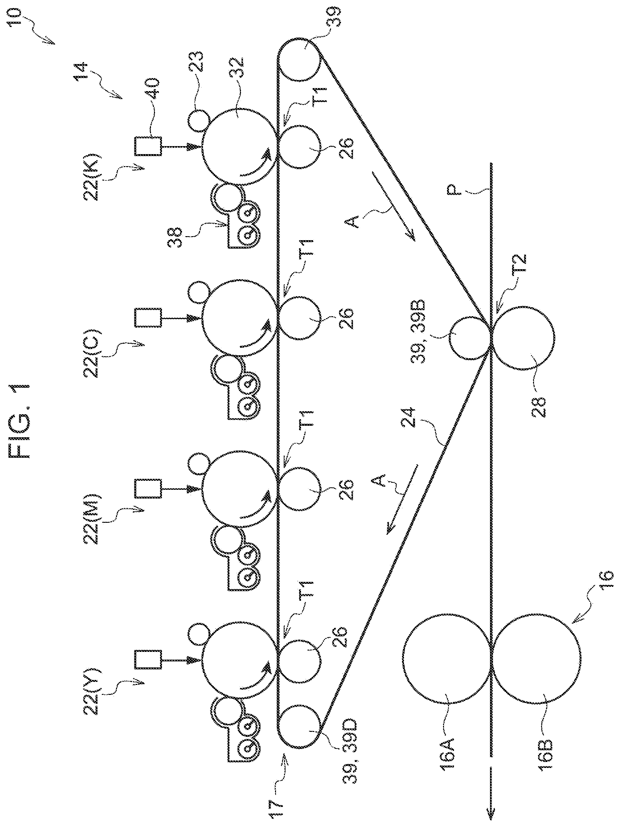
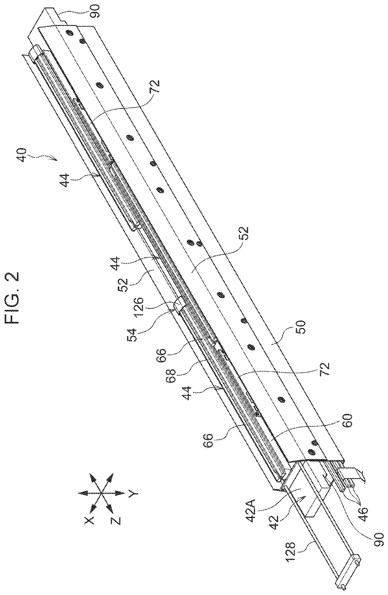
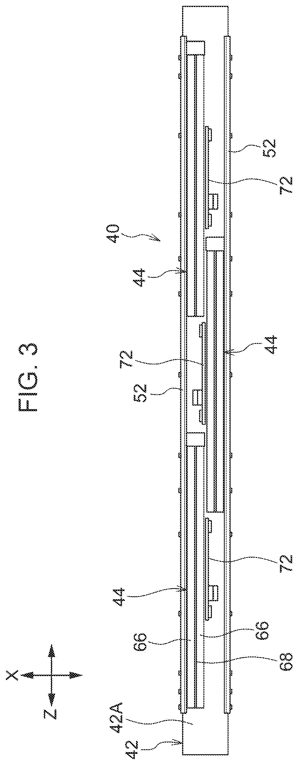
[0019]FIG. 1 is a schematic view of an image forming apparatus 10 including an exposure device 40 according to a first exemplary embodiment. First, the configuration of the image forming apparatus 10 will be described. Next, the exposure device 40 used in the image forming apparatus 10 will be described. Here, the image forming apparatus 10 is an example of a drawing apparatus, and the exposure device 40 is an example of a light emitting device. The image forming apparatus 10 is, as an example, an image forming apparatus that forms an image in plural colors, and is, for example, a full-color printer for commercial printing for which particularly high image quality is required.

[0020]The image forming apparatus 10 is a wide image forming apparatus that can form an image having a width that is larger than the width of a B3 portrait recording medium P (that is, a width larger than 364 mm). As an example, the image forming apparatus 10 can form an image on a rec...

second exemplary embodiment

[0104]Next, an exposure device according to a second exemplary embodiment will be described. In the second exemplary embodiment, elements, members, and the like that are the same as those of the first exemplary embodiment will be denoted by the same reference numerals, detailed descriptions will be omitted, and differences will be described.

[0105]FIG. 9 illustrates an exposure device 150 according to the second exemplary embodiment. The exposure device 150 includes a base 152 and an air supply device 160 that is disposed along the base 152. In the exposure device 150, the base 152 and the air supply device 160 are changed, and the other components are similar to those of the exposure device 40 according to the first exemplary embodiment. That is, the side covers 52, which are provided on the lateral sides of the three light emitters 44, are provided at both end portions of the base 152 in the transversal direction.

[0106]The base 152 is formed of a rectangular-parallelepiped metal bl...

third exemplary embodiment

[0113]FIG. 10 illustrates a drawing apparatus 200 including a light emitting device 202 according to a third exemplary embodiment. Elements of the third exemplary embodiment that are the same as those of the first exemplary embodiment will be denoted by the same reference numerals and descriptions thereof will be omitted.

[0114]As illustrated in FIG. 10, the drawing apparatus 200 includes the light emitting device 202, and a cylindrical member 204 that is disposed so as to extend in the longitudinal direction of the light emitting device 202 and that rotates in a circumferential direction.

[0115]The light emitting device 202 has a configuration similar to that of the exposure device 40 according to the first exemplary embodiment.

[0116]The cylindrical member 204 includes a cylindrical portion 204A and a shaft 204B that extends toward both sides of the cylindrical portion 204A. The shaft 204B is rotatably supported by a frame (not shown), and the cylindrical portion 204A rotates in the ...


PUM


Abstract

A light emitting device includes: a base that extends in one direction and that is formed of a metal block; plural light emitters that are disposed on a front surface side of the base so as to be displaced from each other in the one direction and in each of which plural light sources that are arranged in the one direction are supported by a support that extends in the one direction; and a protective member that is provided at an end portion of the base in a direction intersecting the one direction, that is disposed on a lateral side of the plural light emitters so as to extend in the one direction, and that protects the plural light emitters from outside.

Description

CROSS-REFERENCE TO RELATED APPLICATIONS[0001]This is a continuation of International Application No. PCT / JP2020 / 026720 filed on Jul. 8, 2020, and claims priority from Japanese Patent Application No. 2020-054929 filed on Mar. 25, 2020, the entire disclosures of which are incorporated herein by reference.BACKGROUND(i) Technical Field[0002]The present disclosure relates to a light emitting device and a drawing apparatus.(ii) Related Art[0003]Japanese Unexamined Patent Application Publication No. 2017-177664 discloses an exposure device including a first exposure head and a second exposure head. The first exposure head includes: plural first light-emitting elements that are arranged in a first direction and each of which emits a first light beam; a first optical system that is disposed so as to face the plural first light-emitting elements in a second direction intersecting the first direction and that performs imaging of each of the first light beams that are respectively emitted from ...

Claims


Application Information

Patent Timeline
IPC IPC(8): G03G15/04G03G15/043
CPCG03G15/04036G03G15/0435G03G2215/0407B41J2/447B41J2/455H04N1/036B41J2/45H01S5/40H01L33/00
Inventor KASUYA, YOSUKEKOBAYASHI, TAKAHIKO
Owner FUJIFILM BUSINESS INNOVATION CORP
Why Eureka
Try Eureka